Peak-peak displacement of vibrations greater than diametrical clearance
This article talks about how the peak-peak displacement of vibrations is greater than the diametral clearance. De facto, explained as the amplitude of the peak peak displacement of vibrations measured with a proximitor, on a shaft in a fluid film bearing, numa turbo machine, may be greater than the diametrical clearance of the shaft in the bearing.
The situation in which the peak-to-peak vibration amplitude measured by a proximitor is greater than the diametrical clearance of a shaft in a fluid film bearing (hydrodynamics) It is normal and has clear explanations in the rotor–bearing dynamics.
1 – The proximitor measures the relative shaft–structure displacement, not just the movement within the bearing
The key is to realize that the sensor measures the relative movement of the shaft in relation to the probe, but does not directly measure the relative movement of the shaft within the clearance.
The proximitor is fixed to the machine housing (stationary), but the shaft vibrates in relation to the housing, while the actual orbit of the shaft within the bearing is limited by the radial clearance.
Like this, the movement results from the sum of:
- Shaft movement
- Movement (flexion) of the bearing structure or support
- Dynamic rotor displacements (whirl, whip, own modes)
The sensor does not distinguish between these components.
2 – Rotor movement is not limited by clearance – only the geometric center is
A folga radial (half of the diametric clearance) limits where the center of the shaft can be within the bearing, but the outer surface of the shaft can move much more when the rotor bends (vibration mode), because bending increases the eccentricity of the surface, even if the center remains within the gap.
That is:
- Center of the vein: limited by clearance
- Shaft surface (what does the proximitor see): can move well beyond clearance
3 – Whirl and oil-whip can produce amplitudes greater than the clearance
Self-excited vibrations like:
- oil whirl (≈ 0,42×RPM)
- oil whip (locked to a frequency close to the natural frequency)
can cause large amplitudes on the rotor surface, especially when the rotor resonates.
In such cases, the amplitude can exceed several times bearing clearance.
4 – Rotor bending modes in high speed rotors
When the rotor goes into proper mode (1th mode, 2th mode, etc.), vibration is not a simple rigid displacement of the shaft within the gap.
He deformed, and a point where the proximitor is measuring can move quite a bit, greatly exceeding the radial clearance.
5 – Small movement of the support → large measurement error
If the proximitor housing or bracket vibrates up to 10–20 μm (very common on large machines), this appears as “additional vibration” in the signal.
Example:
- Actual shaft movement: 50 μm pk-pk
- Movement of the structure where the sensor is mounted: 20 μm pk-pk
The proximitor shows:

That is: difference of 40% without the shaft increasing the vibration.
6 – The movement of the structure may be out of phase
The movement of the support may be:
- in the same phase
- in phase opposition
- with any angle
This can:
✔ increase the measured amplitude
✔ reduce the measured amplitude
✔ cause anomalous rotations in the orbit
✔ change the apparent phase
✔ produce the effect of “vibration greater than backlash”
7 – Structural modes influence reading
When the carcass, base or support resonates, the movement of the proximitors' support can become much greater, creating misleading readings.
Typical consequences:
- “Mysterious” amplitude spikes at non-rotor frequencies
- Sudden phase changes
- Deformed or figure-shaped orbits 8
- Increased vibration in one direction but not the other (because of directional structural modes)
8 – In fluid film bearings the problem is relevant
In hydrodynamic bearings the housing:
- Vibrates with its own modes different from those of the rotor
- Can amplify vibrations due to hydraulic loads
- Has low stiffness in certain directions
This further increases the relative measurement error of the proximitors..
9 – As this can cause amplitude greater than clearance
If the proximitor holder vibrates 30–40 μm pk-pk, the measured displacement may seem enormous.
Real example:
- Radial clearance: 0,10 mm
- Real shaft center vibration: 60 μm pk-pk
- Vibration of the structure at the proximitor point: 40 μm pk-pk
Proximitor apparent reading:

If it is in phase opposition it can still give more.
Therefore, the proximitor can show more than the clearance even without contact or serious problems in the rotor.
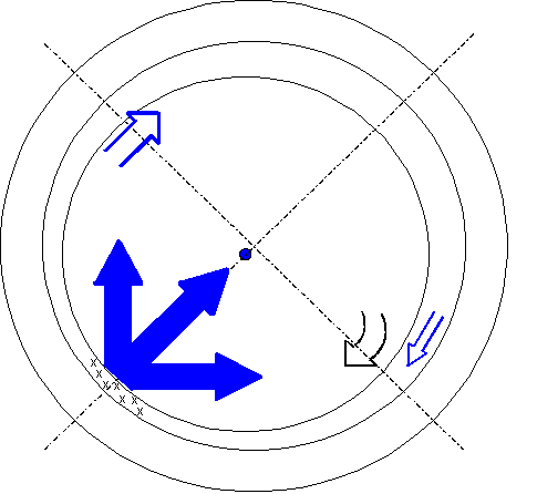
10 -Graphical representation
The following figure illustrates the effect of combining shaft vibration, with the vibration of the point where the proximitor is mounted, on the measurement result.
10 Symptoms that vibrations from the proximitor support are influencing its measurements
Symptoms that the vibrations of the proximitor support are influencing its measurements are:
- Phase change incompatible with phenomena in the shaft
- Orbit measured with “strange” or “blurred” shape
10.1 Phase change incompatible with phenomena in the shaft
The actual shaft vibration in a fluid film bearing has a very stable phase (normally associated with imbalance).
More cases are observed:
- Phase varying with load, temperature or start
- Unstable phase between opposing sensors
- Distorted or “floating” orbits
Strongly indicates movement in the housing.
10.2 Orbit measured with “strange” or “blurred” shape
Carcass movement causes orbits:
- With offset center
- Flattened in unusual directions
- Highly eccentric
- With unexpected “loops”
If the orbit does not correspond to typical oleohydrodynamic behavior (oil whirl/whip), there is participation of the carcass.
11. Direct tests to confirm the influence of the carcass
11.1. Simultaneous measurement: proximitor + accelerometer in the same direction
If the phase or waveform of the proximitor “follows” the housing vibration this is direct proof of contamination in the measurement.
11.2. Comparison between opposing proximitors (X and Y)
If the quadratic sum (magnitude) varies with temperature, load or structural rigidity of the carcass the cause is in the structure, didn't come.
11.3 Modal analysis and Bode
If the proximitor shows:
- increasing amplitude close to the natural frequency of the structure
- typical phase of a mass-spring system
- while the shaft has no corresponding phenomena (no oil whirl/whip at this frequency)
It's the carcass vibrating, didn't come.