Run-Out in Proximity Sensors
This article deals with the Run-Out theme in Proximity Sensors.
1. AIM
This document establishes definitions, acceptance criteria and compensation procedures relating to the phenomenon of relative vibrations (rotation eccentricity) in radial vibration and axial shaft position measurement systems based on inductive proximity probes (eddy current probes), in accordance with the requirements consolidated in the standard API 670 – Machinery Protection Systems and in the norm API 541 – Form-Wound Squirrel Cage Induction Motors, applicable to critical rotating machines (turbines, compressors, large engines and generators).

2. Run-Out in Proximity Sensors – NORMATIVE REFERENCES
- API Standard 670 – Machinery Protection Systems for Petroleum, Chemical and Gas Industry Services (current edition, currently 5th edition);
- API Standard 541 – Form-Wound Squirrel Cage Induction Motors – 500 Horsepower and Larger;
- ISO 21940 (series) – Balancing of rigid rotors;
- ISO 20816 (ISO substitutes 7919/10816) – Assessment of mechanical vibration in machines by measurements on non-rotating and rotating parts;
- End User Purchase Specifications (purchaser specifications), which typically impose run-out limits more restrictive than the regulatory minimum.
3. Run-Out in Proximity Sensors – DEFINITIONS
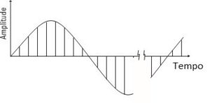
3.1 Total Indicated Runout (TIR) — total variation of the gap signal (voltage/distance) measured by the proximity probe over one complete revolution of the shaft, what not attributable to actual dynamic vibration. Also called runout, or, in the specific condition of low rotation, slow roll runout.
3.2 Mechanical run-out — TIR component associated with physical geometric deviations, including:
- Out of circularity (out-of-roundness) from the probe track (probe track) and/or the current (journal) of the bearing;
- Lack of concentricity between probe track and crankpin;
- Surface defects in the observation area (risks, corrosion, machining marks);
- Misalignment or warping (bow) from the shaft.
3.3 Electrical run-out — TIR component associated with local variations in the electromagnetic properties of the vein material (conductivity, magnetic permeability), arising from metallurgical heterogeneity, residual magnetization, residual stresses or non-uniform heat treatment, even in the absence of any geometric deviation.
3.4 Slow Roll — according to API 541, 52nd edition, section 6.3.3.3, condition in which the rotor of motors/generators with oil film bearings rotates in a range typically between 200 e 300 RPM, speed at which dynamic effects (imbalance forces, oil whirl, etc.) are considered despicable, making the 1X signal measured in this condition representative, by definition, do run-out puro.
3.5 Run-out compensation (Runout Compensation) — vector subtraction process (amplitude and phase, at 1X frequency) or by full waveform of the slow roll signal of the signal measured at operating speed, in order to isolate the real dynamic vibration component.
4. APPLICABLE REGULATORY REQUIREMENTS
4.1 Mandatory synchronous data compensation
According to API 670, section regarding data processing (N.13.2.3), protection monitoring systems must provide run-out compensation for synchronously sampled data with shaft rotation, compensation being acceptable both by vector (amplitude/fase na 1X) as per full waveform.
4.2 Breakdown of TIR components
The total TIR observed in a field measurement results from the superposition of, no minimum, four discrete and independent components:
- Out of roundness of the journal surface,
- Out of circularity of the proximity probe reading zone,
- Lack of concentricity between the two surfaces,
- Electrical run-out
Factory bench testing methods allow us to discriminate these four components individually, enabling targeted corrective actions prior to final machine assembly.
4.3 Probe observation area (probe track)
The standard requires that the surface area of the vein observed by the probe (probe track) meets surface finish requirements and freedom from defects, in a manner consistent with runout limits specified by the purchaser. Purchasing specifications typically seek to reduce slow roll runout to the minimum practicable, This is known to be one of the most difficult requirements to consistently meet during final factory testing., being able, when not answered, generate critical equipment delivery delays.
4.4 Acceptance Limits
The numerical limits of allowable IRR (typically expressed in mils or µm peak to peak, or as a percentage of the vibration alarm value) are not universally fixed by the API 670, being contractually defined by the buyer/specifier based on:
- Machine criticality;
- Amplitude of alarm and vibration trip limits adopted (typically on the order of 10–15 mils / 250–380 µm p-p for alarm and 25 mils / 635 µm p-p for tripping on large critical machines, as per usual API practice);
- Nominal rotation and bearing diametrical clearance.
As a general engineering practice, it is recommended that the IRR does not exceed a small fraction (typically cited in the range of 25% or less) of the established vibration alarm value, so that measurement error does not compromise the margin of detection of real faults.
5. REGULATORY COMPENSATION PROCEDURE (SLOW ROLL COMPENSATION)
- Preparation: rotate the shaft using a turner (turning gear) or controlled start until reaching the slow roll speed range (typically 200–300 RPM as per API 541, or other range defined by the manufacturer where dynamic forces are negligible).
- Reference vector acquisition: record amplitude and phase of the 1X signal (or the complete waveform) in each measurement plane, in this slow rotation condition.
- Storage: the vector (or waveform) slow roll is stored in the monitoring system as a compensation reference.
- Compensation in operation: during operation at rated speed, the system vectorially subtracts the slow roll value from the signal measured in real time, delivering dynamic vibration compensated value, both for protection purposes (alarm/trip) as for diagnostic analysis.
- Periodic revalidation: compensation must be reassessed whenever there is mechanical intervention on the shaft (machining, on the left, bearing disassembly), material change in the probe track region, or signs of non-repeatability of the run-out pattern between matches.
5.1 Compensation validity condition
Slow roll compensation is valid only as long as the run-out is repeatable match after match. If the TIR pattern varies between successive slow roll measurements (new residual magnetization, progressive track wear, permanent thermal deformation), the stored compensation no longer correctly represents the systematic error and must be redone, at risk of introducing additional error rather than correcting it.
6. VERIFICATION AND MITIGATION METHODS
| Action | Normative purpose |
| Visual and dimensional inspection of the probe track | Identify mechanical run-out due to surface defects |
| Residual magnetic field measurement (gaussmeter) on the trail | Identify electrical run-out |
| Discrimination test 4 components on factory bench | Isolate root cause (should have, trail, concentricity, electric) before assembly |
| Surface finish check (roughness) according to the probe manufacturer's specification | Reduce original mechanical run-out in machining |
| Demagnetization of the track region after machining/welding | Reduce electrical run-out |
| Use of a pair of X-Y probes at 90° per measurement plane (as per API practice 670 for critical machines) | Allow orbital analysis and discrimination between run-out and real vibration |
7. CONSEQUENCES OF NONCOMPLIANCE
Failure to properly handle the run-out, not in compliance with API compensation requirements 670, may result in:
- False alarms/trips of the protection system, with unscheduled machine stoppage;
- Real vibration masking (by partial vector cancellation), delaying the detection of incipient faults such as unbalance, misalignment or cracks in shaft;
- Contractual non-compliance against the end user's purchase specifications, with possible impacts on delivery schedule and factory test acceptance (FAT).
8. EXAMPLE – RUN-OUT TO CAUSE STEAM TURBINE TRIP
In the figure below you can see the evolution of the vibration level, during the stop, in the relative vibration sensors of a turbine bearing. It can be seen that when the machine runs below 4650 RPM, the vibration level does not drop below 45μm p-p, which is the run-out of the machine shaft.

Figure 2 – Evolution of the vibration level during stopping, in the relative vibration sensors of the turbine bearing
This run-out can also be seen in the waveform of the same displacement sensors, in the figure below.

Figure 3 – Waveform of the relative vibration sensors of the turbine bearing during the stop 3858 rpm, where you can see the run-out of the 45 μm p-p.
This run-out is also very visible in the orbit measured by these same sensors in 7017 rpm, as seen in the figure below.

Figure 4 – Orbit measured by turbine bearing relative vibration sensors, a 7017 rpm.
The risk seen in the orbit in the previous figure is responsible for a significant part of the increase in vibrations in the final phase of the machine's start-up and which generated a shot, and which can be seen in the graph below.

Figure 5 – Increase in vibrations in the final phase of machine start-up in the Y probe and which generates the trip.
On the X probe, on the contrary, there is a decrease in the level of vibrations.
Comparing the orbit to 7018 RPM with the same measurement 6388 rpm, which can be seen in the figure below, understand why this happens.

Figure 6 – Orbit comparison to 6481 rpm (vertical major axis) it's at 7018 rpm (major axis tilted 45º to the left)
A “pseudo elipse”, described by the orbit when the machine rotates 6481 rpm, has the long axis in the vertical direction. View from the X and Y probe (with the positions marked in the upper right and left corner respectively, both at 45º from the vertical, each to their own side) the peak-peak amplitude measured by the two, is approximately equal.

Figure 8 – Comparison of measurements in orbit 6481 rpm (vertical major axis) it's at 7018 rpm (major axis tilted 45º to the left)
On the other hand, a “pseudo elipse”, described by the orbit when the machine rotates 7018 rpm, has the long axis in the direction of the Y probe. Furthermore, the effect of risk (relative vibrations) also aligns with the Y probe axis, adding the two effects. On the other hand, the orbit presents its minor axis to the X probe. So the 7018 rpm the peak-peak amplitude in the X direction is much smaller than in the Y direction.
That is, the orbit described by the geometric center of the machine shaft, it rotates counterclockwise, during this speed increase, and this effect generates the growth of vibrations according to Y and their decrease, second.
Thus the value of the real peak-peak vibration, of the turbine shaft on the reducer side, without the effect of risk, is lower by about 40 μm peak-peak to the value measured by probe Y and will be close to the upper limit of zone C. Thus, subtracting this value, to the measured value of 143 μm peak-peak, the real vibration value of this bearing, must be in the order of 100 μm peak-peak, falling within what was considered suitable for long-term service.
9. CONCLUSION
The normative treatment of run-out in inductive proximity probes is not an optional refinement, but an explicit requirement for the design and operation of machine protection systems according to the API 670. Correct discrimination between mechanical and electrical run-out, combined with vector slow roll compensation according to API 541/670 and the periodic revalidation of this compensation, is a necessary condition to guarantee the integrity of vibration data used both in protection (alarm/trip) as well as in condition diagnosis of critical rotating machines.