The API norm 670 – machine protection systems
The API norm 670
The API norm 670, for machine protection systems do American Petroleum Institute, is widely recognized in the industry and is actively used by regulators and operators worldwide.
The API norm 670 describes the minimum requirements for a machine protection system (SPM) which measures shaft and housing vibration, axis position, spindle rotation speed, piston rod drop, over-speed, return (surge) and / or critical machine temperatures. To reduce the likelihood of misinterpretation, or API 670 also includes detailed instructions that apply when designing, Apply, test and maintain machine protection systems.
Observation: this article makes reference to the API 670, 52nd edition (November 2014) to highlight and discuss some of the general design specifications described in the section 4 this standard. O bold type is used to refer to the corresponding sections and section numbers (4.x) are added when useful.
This article focuses mainly on aspects related to vibration monitoring.
The numerical indications mentioned below, correspond to the various points of this standard, in its version from two thousand to fourteen.
This article belongs to a series, which constitutes the support material for the course on vibration analysis in turbomachinery. Links to the other articles can be found on here.
History of the API Standard 670
First edition: June of 1976
The initial development of the API 670 was driven by the need for machine users to specify proximity probes and monitoring systems pre-installed in their machine packages that conform to basic functional requirements, performance and interchangeability. This helped ensure that sensors from one manufacturer would work with monitoring systems from another manufacturer.. It also ensured that the cable lengths of the transducer systems, the probe settings, tip diameters and oscillators/demodulators had a limited number of permutations to help reduce spare parts requirements. The First Edition only covered radial vibration and axial position measurements (impulse). It did not encompass the absolute vibration (box), bearing temperature or any other measurement introduced in later editions of the standard.
Second edition: June of 1986
The second edition introduced content related to bearing temperature measurements.
Third edition: November 1993
a separate standard (API 678) was released in May 1981 and covered vibration monitoring systems based on accelerometers. Like this, during a period, two separate API standards coexisted – one for systems based on proximity probes and one for systems based on accelerometers (seismic). The two standards had considerable overlap and represented redundant efforts to be maintained.. The main objective of the third edition working group was to, therefore, merge the two standards into a single document. Consequently, a API 678 was withdrawn from use with the publication of the third edition of 670. The third edition also introduced new appendices that cover supplier documentation and design requirements., documentation requirements and field testing, accelerometer application considerations and gear vibration considerations.
Fourth edition: december of 2000
Fourth Edition focused on content that had become obsolete and assumed analogue technology instead of the latest digital technology (such as indicators that can no longer be physical bulbs or LEDs). Introduced specified options to separate the machine protection system into smaller functional subcomponents that can be physically separated from each other (as a non-integral viewfinder), but kept a “contiguous system” as default. It also introduced the inclusion of overspeed detection instruments and piston rod drop measurements.. Sensors have been extended to include magnetic pickups for speed measurements, and appendices have been added for considerations of setpoint multipliers and electronic overspeed detection systems. The types of measurements covered by the standard have become long enough that it is tedious to list them all as part of the title.. Like this, the norm was called “Machine Protection Systems”.
Fifth edition: November 2014
The fifth edition represents a significant revision of the standard and organizes the protection system into subsystems as follows:
- Vibration/Position/Temperature/Rod drop (section 7)
- Overspeed detection systems (section 8)
- surge detection systems (section 9)
- emergency stop systems (Score 10)
- End stop elements (10.8)
- other entries (10.7.2)
some sections (1-6, 11, 12) now concern all these subsystems, while other sections (7-10) only concern selected subsystems, as mentioned above.
Surge detection and emergency stop systems are entirely new, such as the K-Q attachments. Annex No, by itself, adds a tutorial 50 status monitoring pages; Appendix L adds a tutorial on 20 Security Integrity Level pages (SIL); and Appendix P adds a tutorial on 10 pages on monitoring reciprocating compressors. The page count of other new attachments is summarized in Table 1 on previous page. Besides that, the normative content related to speeding is substantially expanded. As a result, the page count of the standard has increased from 96 pages in the Fourth Edition for 244 pages in the Fifth Edition. Besides that, the use of color is now present in the illustrations. Previous editions of the standard were limited to black and white illustrations.
STANDARD SPECIFICATIONS
POINT FOUR – GENERAL PROJECT SPECIFICATIONS.
segregation (4.8)
Independence and separation of systems, components or parts is an important design concept underlying the entire standard. For example:Segregation requires that the Machinery Protection System be completely separated from any other systems, like another protection system, control systems or condition monitoring systems (MACHINE MONITORING SYSTEM).
- Inside the Machine Protection System, all machine protection circuits are normally wired (wireless communication is not allowed here) and interconnections with other devices in the automatic machine stop circuit, are implemented through system output relays.
- A problem with a measurement chain, input channel or signal processing should not affect any other channel. This applies to system power supplies, as well as the power supplies of individual sensors. To mitigate these failures, machine protection systems often use redundant power supplies.
- The means of digital communication for systems outside the Machinery Protection System, as a Condition Monitoring System (SMC), must not affect the protective functions of the machines. This also applies to buffered analog outputs (“raw”), even in the event of a short circuit at these outputs.
- Similarly, Interchangeability implies that it must be possible to physically and electrically replace the components of the Machinery Protection System, in-situ, without leaving the measurement accuracy requirements.
The Machinery Protection System must be separate and distinct from all other control or protection systems, so that its ability to detect an alarm within the required response time on any monitored parameter and activate the system output relays. (4.8.1)
The intent of this subsection is to prevent the Machine Protection System hardware from, be combined with hardware from other control and automation systems, thereby eliminating common cause failure modes and protecting the machine in the event of failure of its associated machine control system or failure of the process control system. It is not intended to prohibit the inclusion of condition monitoring functionality in the Machinery Protection System, provided that the failure of these functions does not affect the protective functions.
Wireless technologies must not be used for protective functions.(4.8.2).
Power supplies
All machine guard monitoring systems must be capable of meeting the accuracy requirements specified in Table 1 of the norm, with an input voltage to the power supply of 90 VAC rms a 132 VAC rms or 180 VCA rms a 264 VCA rms, switch selectable, with a mains frequency of 48 Hz a 62 Hz. If specified, The following power supply options can be used:(4.10)
- 19 Vdc a 32 Vdc,
- 14 Vdc a 70 Vdc,
- 90 Vdc a 140 Vdc.
All power supplies must be capable of withstanding an indefinite short circuit at their outputs without damage (4.10.4).
All transducer power sources must be designed to prevent a failure in one transducer circuit from affecting any other channel (4.10.5).
Features/Functions of the Machine Protection System (4.11)
no minimum, Each machine protection system must be equipped with the following features and functions (4.11.3).
- A method of activating all indicators for testing purposes;
- An internal clock with provisions for remotely setting the time and date via the digital communication port;
- All modules that can be removed and inserted while the system is energized without affecting the operation of other unrelated modules or causing damage to them.
Each machine protection monitoring system must have, no minimum, the following features and functions (4.11.3):
- A method of energizing all indicators for testing purposes;
- An internal clock with provisions for remotely setting the time and date via the digital communication port;
USE: Internal clock time setting or synchronization must be done with the master remote clock and the monitor system internal clock for event time correlation, effective;
- All modules can be removed and inserted while the system is powered without affecting the operation of other unrelated modules or causing damage to them.
Machine protection systems must include the following signal processing functions and outputs (4.11.4)
- Isolation to prevent a failure in one transducer from affecting any other channel.
- A means of indicating internal circuit faults, including failures in the transducer system, with externally visible circuit fault indication for each individual channel. A no-fault condition must be indicated positively (for example, illuminated). For each monitoring system, a common circuit fault relay must be provided.
- A defect in a circuit must not initiate a stop or affect the stop logic in any way, except in the cases indicated in 7.4.1.5 e 7.4.2.5.
- Individual unfiltered and buffered output connections for all transducers in the system (except temperature), via BNC plugs on the front panel and connections on the rear panel. If specified, the monitoring system may use non-BNC connectors or locations other than the front panel.
- If specified, An analogue output must be provided. 4 mA a 20 mA DC for each measured variable used for machine protection, in addition to the digital output.
- If specified, A digital communication port must be provided for data transmission between the machinery protection system and compatible condition monitoring software.
A machine protection monitoring system must include the following alarm/stop functions (4.11.5).
- For each channel, the alarm values (alert) and stop (danger) are individually adjustable over the entire monitored range.
- One alarm output (alert) of each channel or channels voted to the alarm relay (alert) corresponding. Non-voting logic is required (OR).
- One stop exit (danger) of each channel or channels voted to the stop relay (danger) corresponding, as referred to in 7.4.1.4, 7.4.2.4, 7.4.3.6 e 7.4.5.4.
- The time required to detect and initiate an alarm (alert) or a stop (danger) relative vibrations 100 ms. Relay activation and status notification by the monitoring system must be fixed by the delay time specified in point 7.1.5, align to).
USE: The response time requirement of 100 ms applies after the system has executed any signal processing and/or filtering algorithms for disturbance rejection.
- Stop indication (danger) for each channel indicating the channel's alarm status independent of voting logic. The stop indication (danger) should be a positive indication (for example, illuminated when the channel violates its stop setpoint). If specified, stop indication (danger) must comply with the functioning of the voting logic.
- If specified, A tamper-proof means must be provided to disarm the stop function (danger) and a visible indicator (positive indication, for example, lit when disarmed) for each channel. Any tripped condition must activate a common relay located in the rack or power supply. This relay must comply with point 4.12 and can be used for remote advertising.
USE: This requirement is intended to be used to remove, of the service, a faulty or intermittent channel.
- Local and remote access to reset alarm conditions (alert) and stop (danger) blocked. For rack systems, A switch on the front panel and connections on the rear panel must be provided.
- A means of identifying the first exit alarm (alert) and the first exit stop (danger).
If specified, the selected channels (or all channels) of the monitor must be available in two additional configurations that utilize redundancy or other means (4.11.6.)
- A single circuit failure (except power supply and monitoring system power supply) will only affect the offending channel and will not affect the state of the alarm relays.
A machine protection monitoring system must have the following indications (4.11.7)
- energy state,
- digital communications connection status
- system circuit failure
- system stop (danger)
- alarm (alert) of the system,
- system stop function (danger) outdated.
System output relays (4.12)
- The output relays described in this point must be used to interconnect the machine protection system with all other devices used as part of the automatic stop circuit..
- Optional digital interfaces 4.11.4 f) e 4.13 and the analog outputs of 4.11.4 d) e 4.11.4 e) must not be used as part of the automatic stop circuit.
- Unless otherwise stated, the output relays must be of the electromechanical type sealed from epoxide.
- If specified, Any of the following relay types may be supplied in place of epoxy sealed relays.
- Hermetically sealed electromechanical type;
- Solid state type. If a solid state relay interface is proposed between systems, The salesperson responsible for the unit must provide a complete analysis of the relay's capabilities and requirements to ensure reliable operation.
- The relay control circuit must be capable of being modified in the field to be normally de-energized or energized. Factory default must be de-energized for alarm and energized for shutdown.
- All relays must be double throw type with electrically insulated contacts and all contacts available for wiring.
- Shutdown relays (danger), alarm (alert) and circuit failure must be able to be replaced by locking (latching – manual reset) or not lock (non -latching – automatic restart). The “latching” shape must be normal.
- The circuit fault relay must be normally energized. A failure in the transducer system, in the monitoring system, on the primary power supply or redundant power supply must de-energize the circuit fault relay.
- The contacts must be sized for a resistive load of 2 amperes a 120 VAC, or 1 ampere a 240 VAC, or 2 amperes a 28 VDC for a minimum of 10.000 operations. When connecting inductive loads, arc suppression must be provided to the load. If specified, contacts with a resistive load of 5 amperes a 120 VAC.
- For stop output relays (danger) normally de-energized, a power outage [direct current output power (CC)] should not transfer the shutdown relay contacts (danger), regardless of the mode or duration of the interruption.
- Each monitoring subsystem in the MACHINERY PROTECTION SYSTEM (free from speeding) must have a means to disarm the stopping capacity of the subsystem, in accordance with the following.
- Can be internal or external to the monitor subsystem.
- It must be inviolable.
- A tripped condition must be announced locally in the monitor subsystem via positive indication (for example, lights up when disarmed).
- Operating or maintaining the monitor subsystem in disarmed mode, including replacing the power supply, you must not turn off the machine (see note).
NOTE This feature is intended for use only during maintenance of the monitoring system.
- A disarmed condition must be available for remote annunciation via the digital communications link. 4.13.
- If specified, Two sets of insulated external annunciator contacts must be provided.
Digital communication (4.13)
- Must be provided at a communications port, a digital output representative of each measured variable. A short circuit of this output must not affect the Machine Protection System and, the exit, must follow the measured variable and remain at full scale as long as the measured variable is equal to or greater than full scale. Unless otherwise specified, the protocol used for this standard digital output must be Modbus.
NOTE This output is intended to transmit the status of the Machinery Protection System, proportional values and other data for process control and automation systems as part of their operator trending and display environments. It is not designed nor intended to replace point relays. 4.12 for the purpose of protecting machines. Relays are the only acceptable method of interconnecting the Machinery Protection System to other devices used to execute a shutdown command (4.12.1). See also Annex N.
- If specified, any one or more of the following elements must also be available from the point's digital communications link 4.13.1:
- Alarm channel status or absence of alarm;
- Armed/disarmed stop status (maintenance bypass) of the monitoring system.
- Alarm storage to store the time, date and value for a minimum of 64 alarms;
- Channel value with ±2 resolution % of the full range;
- Measured value as a percentage of alarm values (alert) and stop (danger) up until 1% of resolution;
- Channel status: armed/disarmed.
- Transducer ok limits;
- Hardware and software diagnostics;
- Communication link state;
- Alarm values;
- Static backlash voltage value, when applicable;
- Current system time, timestamp and event date for all transmitted data;
- System entry record to include date, hour, individual access code and change log;
- Invoked setpoint multiplier.
4.16 System security, safeguards, self-tests and diagnostics
- Controlled access for monitoring system adjustments must take the form of a programming access key located on the front of the monitoring system rack or through software (that is, password protection).
- The configuration must be stored in non-volatile memory so as not to be lost in the event of a total loss of power to the monitor system.
NOTE When configuring a system over the network, password protection alone may not prevent accidental transfer of a new configuration (resulting in a possible machine shutdown condition). If this is a concern, both a passkey and password protection should be considered.
- Machine protection monitoring system modules must have self-test capability.
- The machine protection monitor system shall maintain an event list to record module/system alarms and diagnostic test results. This list of events must be:
- Stored in non-volatile system memory;
- Maintained in case of total loss of power or loss of communications.
reliability (4.17)
The seller must indicate in the proposal any component designed to have a finite useful life.
SENSORS AND TRANSDUCERS (5)
ARRANGEMENT OF SENSORS AND TRANSDUCERS (6)
VIBRATION MONITORING SYSTEMS (7)
- Unless otherwise specified, signal processing/ alarm/ integrity comparison, the display/indication and all other features and functions specified in section 4 must be contained in an adjacent compartment (frame) (7.1.2).
- no minimum, Each monitoring system must have the following features and functions (7.1.3).
- Unless otherwise specified, signal processing/alarm/integrity comparison, the display/indication and all other specified features and functions must be contained in an adjoining compartment (frame). With buyer's approval, a system may be provided that is not contained in an adjoining compartment (frame) and that meets all other requirements and functionalities of a predefined system.
- no minimum, Each monitoring system must be equipped with the following features and functions:
- An installation design that guarantees that a single circuit failure (except power supply and monitor system power supply) should not affect more than two channels (regardless of the channels available on the monitor module) shaft radial vibration, axial position, carcass vibration, speed indicator tachometer or six temperature channels or rod drop in a single machine housing.
USE: The intent of this requirement is to ensure an installation design that does not lose all monitoring in a machine box in the event of a single circuit failure..
- In all radial vibration channels of the shaft, axial position, rod falling and casing vibration, associated outputs and displays must have a minimum resolution of 2 % full scale. The temperature channels, associated outputs and displays must have a resolution of 1%, regardless of engineering units. Tachometer and electronic ODS channels, the associated outputs and informants must have a resolution of 1 rpm.
- Electrical or mechanical adjustments for zeros, gains and alarm setpoints (alert) and stop (danger) that can be changed in the field must be protected by controlled access. The means of adjustment, including the(s) connection(ions) for a portable configuration device, must be accessible from the front of the monitoring system. During adjustment, the alarm and stop functions of the monitoring system must be, manually or automatically bypassed.
- It is allowed to install modules to monitor more than one train of machines in the same rack (chassis) of the monitoring system. However, each set of machines must have specific monitoring modules. When multiple machine trains are monitored using a single rack, the monitoring system must support the ability to accommodate multiple phase reference transducer inputs from each of these machine trains.
- The monitoring system must include digital and/or analog interfaces capable of serving an external host computer for the implementation of a Condition Monitoring System.
- A control system must include the following signal processing functions and outputs (7.1.4).
- Gain adjustment for each shaft radial vibration and axial position channel,
- The factory preset gain setting should be 7,87 mv/mm (200 mv/mil).
- A monitoring system shall include the following alarm and integrity comparison functions (7.1.5).
- Fixed deadlines for activation of the stop relay (danger) that can be changed in the field (through controlled access) to require a sustained violation of 1 a 3 seconds. A delay of 1 second must be standard.
- Alarm indication (alert) for each channel or pair of axial position channels.
- A monitoring system must include a dedicated, integral screen capable of indicating the following (7.1.6).
- All measured variables used in the protection function
- Alarm setpoints (alert) and stop (danger);
- DC gap voltages (for radial shaft vibration, axial position, piston rod drop and speed indicator tachometer.
- The monitoring system display must be updated at a minimum rate of once per second (7.1.7.)
- The display can be an analog indication, digital, graphic or other, as specified by the buyer (7.1.8)
- Unless otherwise stated, the monitoring system must indicate (7.1.9):
- The highest radial vibration of the shaft in each bearing,
- All axial position measurements,
- The highest temperature for each machine box,
- Highest casing vibration for each machine housing,
- All standard speed indications and overspeed detection channels,
- The highest rod drop channel for each machine box.
- If a blind monitor system is specified, a non-integral display can be used, as long as it meets all the same measurement and status indication criteria required for the full version (7.1.10.).
- Power supplies – The output voltage for all oscillator-demodulators must be –24 Vdc with sufficient regulation and ripple suppression to meet the accuracy requirements specified in Table 1 (7.2).
System output relays (7.3)
- The output relays described in this point must be used to connect the machine protection system monitor to all other devices used as part of the automatic stop circuit.. The point's optional digital interfaces 4.11.4 f) e 4.13.1 and optional analog point outputs 4.11.4 e) must not be used for machine protection purposes (7.3.1.)
- no minimum, a pair of relays must be provided – of alarm (alert) and stop (danger) – for each of the following types of variables monitored by set of machines (7.3.2):
- axial position,
- radial shaft vibration
- carcass vibration,
- bearing temperature,
- piston rod drop.
- One circuit fault relay must be provided per monitoring system (7.3.3).
- Monitoring radial vibrations in shafts (7.4.1)
- The complete range for monitoring shaft radial vibrations must be 0 a 125 μm (0 a 5 thousand) actual peak-to-peak displacement. Peak-to-peak values calculated from any other intermediate value or calculated measurement are not acceptable, other than the transducer or signal interface. If specified, the optional full scale default range should be 0 a 250 μm (0 a 10 thousand) of actual peak-to-peak displacement (7.4.1.1.)
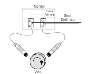
- Radial shaft vibrations must be monitored in paired orthogonal channels (“X-Y”) from the two transducers mounted on each bearing 7.4.1.3.
- The shaft radial vibration stop system must be field changeable, so that a (single logic) or both (double vote logic) orthogonal signs (“X-Y”) of the transducer must persist at or above the setpoint to activate a stop relay (danger). The logic of double voting (two in two) must be standard (7.4.1.4.)
- If specified, single vote logic must be provided (one in two) (7.4.1.5).
- If specified, a threshold multiplier function must be provided, with controlled access, with the following capabilities (7.4.1.6.)
- Triggering by an external contact closure causes the alarm thresholds to (alert) and stop (danger) are increased by an integer multiple, two (2) or three (3). A multiplier of 3 (three) will be standard.
- A positive indication must be provided (for example, light on) in the monitoring system when the multiplier is invoked.
- Raising the setting should not attenuate the actual input signal or alter the proportional digital or analog outputs that represent the channel amplitude.
- Raising the alarm must not attenuate the actual input signal or alter the proportional digital or analog outputs that represent the channel amplitude.
- Changing a vibration measurement to arithmetically subtract (delete) mechanical or electrical run-out or electrical noise. (7.4.1.7)
- If specified, a speed indicator tachometer must be provided. Must have the ability to record and store the highest rotational speed measured (rpm), known as peak speed. If specified, controlled access reset capability for the peak speed function must be available both locally and remotely (7.4.6).
- The system must accept inputs from normal probe transducers or magnetic speed sensors (7.4.6.3)
MONITORING THE CONDITION OF MACHINES – ANNEX N (informative)
This annex discusses the function and requirements of Machine Monitoring Systems and offers recommendations for monitoring methods., intervals, parameters to measure and evaluate and data to record. Attention – the function of a Machine Protection System, as described in the normative sections of this standard, shall not be compromised or impeded in any way by the implementation, function or malfunction of a Machine Monitoring System.
SPECTRUM SAMPLING REQUIREMENTS
The spectrum sampling requirements are as follows (N.13.2.3)
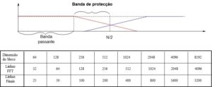
- a) Resolution – Spectrum resolution increases with the number of spectral lines used. This means that the greater the number of spectral lines, more information the spectrum contains. However, if more spectral lines are used, measurement takes longer and more memory is used to store the spectrum. High-resolution measurements are suitable for applications where it is necessary to distinguish between two closely spaced vibration frequencies (that is, engine slip frequencies) or when Fmax is too large. For recording speed ascent and descent, a definition of 400 spectral lines is typically suitable. Besides that, a minimum of 800 spectral lines or higher for spectra measurements.
- Frequency range (Fmax)-Fmax is the maximum frequency presented in the spectrum. Or, more specifically, the range of frequencies, from zero, in which the vibration amplitudes are presented. In general, the higher the operating speed of a machine, The higher the Fmax will have to be to capture all the crucial information.
- Eccentricity compensation must be provided for data collected synchronously.
ENVIRONMENTAL
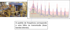
Impact spike detection (N.13.2.14) – Damages to the gearbox and bearings generate characteristic impact signals that, often, are not visible in a typical FFT measurement. Instead of using a typical FFT measurement, other parameters can be used, like the surrounding, to analyze the fault.
WAVEFORM SAMPLING TYPES (N.14.1)
The system must be capable of synchronous and asynchronous sampling.
Synchronous Sampling (N.14.2) – Synchronous sampling must have the following:
- At least 100 sampling points per revolution at maximum speed;
- Sample length of at least 8 revolutions;
- No anti-aliasing filters;
- x and y probes sampled simultaneously with phase reference;
- Option to time synchronous average waveforms with at least 16 media, unless the system does not need averaging;
- Bandpass filtering available for 1/2x shaft speeds, 1x, 2x and 3x and low-pass filtering with corners available for 1x spindle speed, 2x e 3x. Care must be taken to ensure that there is no unwanted phase shift of the data, as the change may be caused by filters;
- Full spectrum plots showing forward and reverse components are valuable, as they have an orbit shape and relationship of components in the frequency domain.
Asynchronous sampling must have, at least, 2048 sampling points (block dimension) (N.14.3).
SAMPLE AND PHRASE RECOMMENDATIONS (N.16.3)
- Global amplitudes must be measured and expressed as acceleration, speed or displacement.
- no minimum, Users should monitor and trend global magnitude and 1X and 2X magnitude values.
- If a reference is available, the values of phases 1X and 2X must also be monitored and presented as a trend.
- Monitor and trend other values as appropriate for the machine
ALARMS
no minimum, The analysis system must provide the following alarm capabilities (N.16.4.2).
- Two level alarms with the following operators:
- greater than,
- less than,
- within the range,
- out of lane.
- Acceptance region alarms for vector measurements.
- Rate of change alarms.
- Alarms must be assignable to any measured value.
- Alarm annunciation capabilities shall include:
- indication on the screen,
- sound indication,
- automatic communication,
- remote notification via email or other communication.
FREQUENCY DOMAIN ANALYSIS (N.16.4.3)
The following minimum frequency domain graphing capabilities shall be provided:
- Frequency spectra in which amplitudes, accelerations, linear speeds or displacements are presented versus linear frequency, expressed in cycles per second (Hz), cpm or orders;
- Waterfall Charts, with at least 50 spectra presented as a function of time;
- Waterfall charts with at least 50 spectra presented as a function of speed.
TEMPORAL WAVEFORM ANALYSIS (N.16.4.4)
The following minimum time domain presentation capabilities shall be provided:
- a) temporal waveform plots of unfiltered data;
- b) temporal waveform plots of time synchronous average data;
- c) orbit charts of unfiltered data;
- d) synchronous data orbit charts (1X, 2X) or running speed;
- e) graphs of time-synchronous mean orbits;
- f) Drift compensation capabilities for synchronously sampled data (that is, slow rotation compensation, thermal arc, etc.).
CRITICAL SPEED ANALYSIS (N.16.4.5)
When monitoring turbo-machinery, operating above the first critical speed of the machine, must be provided, the following minimum transient data presentation capabilities:
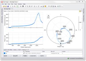
- Bode plot for transient velocity data;
- Polar plots for transient velocity data;
- Axis centerline plots,
- Polar graph of the position of the shaft center line inside the bearing;
- Gap Voltage Plots.
EXCEPTIONAL CAPTURE
For an online system, the data monitored in normal operation, must be captured and stored in an exceptional manner, for example, whenever an alarm condition occurs or when the parameter value changes more than a predefined value. There should also be an option to store time-based data, for example, once an hour, once a day, once a week. The stored data must be kept in the database for at least 24 months. Vibration-related data must include, when available (N.17.1.1):
- Amplitude global,
- Operating speed amplitude and phase,
- Amplitude and phase of the speed of two runs,
- Backlash tension,
They must be kept, too, additional measurements that are key indicators of condition or failure for each specific machine. Non-vibration data should include temperatures, flow rates and bearing pressures. (N.17.1.2).
DATA STORAGE
Detailed data storage for normal operation (N.17.2) – The system must provide storage of the following data at a minimum interval of at least once a day:
- Phase-Referenced Time Waveforms,
- Time Synchronous Waveforms,
- Average spectra (eight averages).
Data storage for start/stop (N.17.3) – When monitoring turbomachinery operating above the first critical machine speed, the system must collect and store vibration-related data, as specified in N.19.3, in deceleration and starting at a rate of each 50 rpm or less. Besides that, a set of data, as specified in N.19.4.4, must be obtained when the machine reaches operating speed.
Data storage for known machine issues (N.17.4) – The system shall provide the ability to change the range of data collected in N.19.3 and N.19.4.4 for startup or problem machine monitoring.
When monitoring turbomachinery operating above the first critical machine speed, the monitoring system must provide transient data collection and analysis capabilities. no minimum, the system must provide the following capabilities. For transient monitoring, it must be possible to monitor and store data on all monitored channels continuously during machine start-up and deceleration. (N.17.5.4.1)
Transient Data Extraction – When transient data is captured on a field device, it must be possible for the user to perform an “on-demand” upload of any stored data. Users should also be able to schedule periodic interrogation of the device with subsequent automatic data loading. (N.17.5.4.2)
Transient Data File – The stored transient data must be capable of being archived and used as reference data. For example, recall the archived transient waveform, drag and drop over live or stored waveform for comparison. (N.17.5.4.3)
Viewing Transient Data – Transient data that has been archived must be viewable for the purpose of reviewing a start-up, stoppage or anomaly that occurred during the normal operation of the production state. Archived transient data must be viewable in the graphs described in N.17.5.5. (N.17.5.4.4)
Online systems must be capable of operating in “live” or near real-time mode, displaying the following graphics with typical refresh rate of at least once per second, a 3.000 rpm and above. The live mode, will not affect normal data collection, data storage or transient data capture. The installments are as follows (N17.5.5.1).
- Wave shape,
- Spectrum,
- Orbit,
- Shaft center line,
- Waterfall,
- Water fall
- Nyquist,
- Bode
Charting options should include orbit filtering and Bode plots, defining the deviation and specifying the clearance for the shaft centerline define acceptance regions in Nyquist plots, waveform eccentricity subtraction and vector eccentricity subtraction must be able to be stored, retrieved and applied to graphics. (N.17.5.5.2)