Analysis of misalignment vibrations
1 – Analysis of misalignment vibrations – introduction
A Vibration Analysis the misalignment of a machine, common vibration analyzer, is an important preliminary to the next step, which is your alignment. Misalignment is one of the most common defects that generate excessive vibrations in machines.. Therefore, anyone who wants to understand the dynamic behavior of equipment in operation must have a reasonably complete understanding of this phenomenon.. This is essential to successfully implement a program of predictive maintenance.
Misalignment in its various forms is undoubtedly one of the most common anomalies in any group of machines..
The understanding of its effects is extremely important for the elaboration of a correct diagnosis regarding the abnormal behavior in a machine..
2 – Definition of misalignment and its origins
Misalignment can basically occur at two levels:
– Misalignment of a shaft in your bearings
- Mismatch between shaft symmetry axis and bearing symmetry axis.
– misalignment of transmissions
- Non-coincidence between the axis of symmetry of two collinear shafts
- Lack of parallelism between shafts
- Incorrect distances
- Incorrect axial position
- Incorrect perpendicularity
Its origin can be different.:
– Poor positioning in manufacture or assembly
- From the bearings of a shaft, between if
- Relative to other veins (transmission misalignment) – engagements, gears, straps, etc.
– deformations
- * Thermal effects on the shaft
- * Thermal effects on the bearing support structure.
- * Warp on the machine support surface
- * Warping in the machine structure
- * Pipe induced warping
3 – Misalignment effects
3.1 – Between Couplings
In the figure 1 presented below you can see the effect of an angular misalignment.
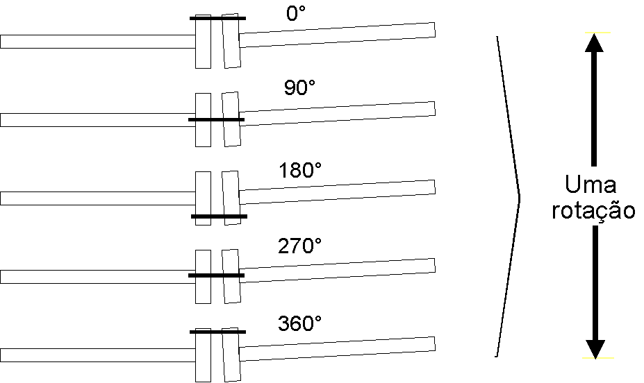
It can be seen that the generation of an approximation force of the veins will occur., in the axial direction, in each rotation. It will be, therefore, natural occurrence of axial vibrations.
In the figure 2 presented below, one can see the effect of a lack of collinearity.

It can be seen that the generation of an approximation force between the veins will occur., in radial directions, twice in each rotation. It is also seen that this force has a predominant direction.
In practice, these isolated effects are rarely found.; it is quite common to find your combination.
are considered, therefore, Misalignment symptoms the following:
- – Abnormal vibrations in the axial direction.
- – Abnormal vibrations at twice the rotation speed.
- – Abnormal directionality of vibrations, contrary to what would be expected given the stiffness of the bearings.
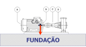
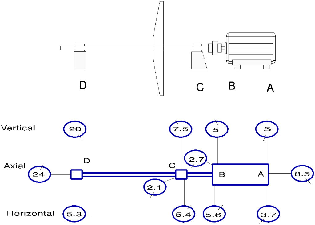
Below you can see the Global Levels of Vibrations in a machine misaligned in the coupling.
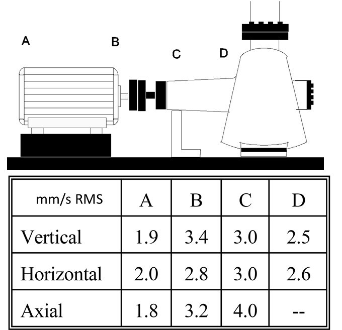
Note-se:
a) Vibrations are greatest in the bearings close to the coupling.
b) Strong vibrations in bearing C, in the axial direction.
c) Or facto no electric motor, in bearing B, vibrations are greater vertically than horizontally, contrary to what would be expected considering only the rigidity of the engine structure.
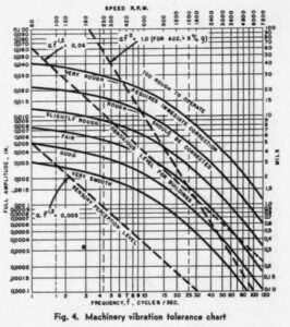
In the figure 4 it can be seen that when you have a force to rotate with the shaft, as in the case of imbalance, misalignment vibration analysis figure. misalignment vibration analysis figure. Misalignment is an anomaly that generates a directional force.

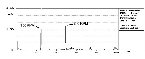
Below you can see a spectrum, that measured in the axial direction of a machine, next to a bearing, is a very strong symptom of misalignment – the 2nd harmonic of the rotational speed is greater than the first.
In the figure 6 you can see the amplitude (inside each circle) and the phase (marked by a cross in each circle) from component to rotational speed, measures in the three directions, in all bearings, on a machine with a coupling misalignment (teeth coupling).
Note the following aspects:
- – phase difference of 180 degrees in the measurements on the motor in the vertical direction
- – I'm going horizontal
- – Strictly equal phase for measurements in the same direction on the bearings on both sides of the tooth coupling (that was blocked).
In these circumstances it can be considered that the coupling, toothed type, was absolutely blocked and caused the two bearings attached to the block to vibrate. Simultaneously, it forced the motor to an oscillatory movement..
Thus, it is normally considered that phase differences of 180 degrees ( and also from 0 in couplings that lock) are symptoms of misalignment.
3.2 – Analysis of misalignment vibrations – Warped Shaft and Bearing Misalignment
A bent shaft can cause misalignment and also imbalance. The following figure shows the effect of a shaft warping..
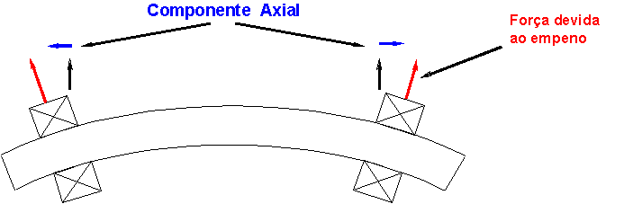
It is therefore natural that vibrations in opposition of phase arise in the axial direction.. In radial directions it is natural that the effect of unbalance due to warping is predominant.
In the figure 8 you can see the phase and amplitude of the vibrations at the rotation frequency of a fan with a hot bent shaft.
Note the vibrations in phase opposition., in the axial direction, on bearings C and D, which are those of the bent shaft. This machine due to warping was unbalanced. Anti-vibration supports explain phase opposition in bearings C and D, in the horizontal direction.

An effect that from a vibration point of view at all resembles that of a bent shaft is the misalignment of bearings.. The following figure shows schematically its effect..
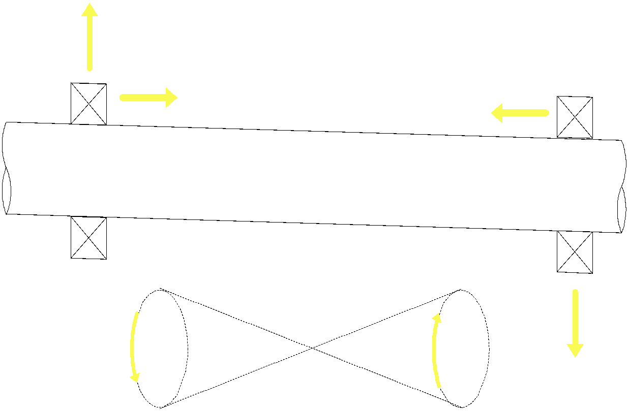
There will be a phase difference of 180 degrees between measurements in the same radial and axial direction.
4 – Analysis of misalignment vibrations – Measuring the vibration phase and using the strobe
The intended purpose with phase measurement is to visualize the movement of the machine while vibrating at a certain frequency.. Take as an example what you see in Fig. 10.

Assume that the motor was vibrating in the horizontal direction, at the rotation frequency, with the vibration profile defined in the Hypothesis 1. When the vibration sensor was placed at different measurement points along the motor, the amplitude of the rotational speed would follow this profile.; larger amplitudes at the ends, close to the bearings and smaller amplitudes in the intermediate positions. If the phase of vibrations were measured, this should always be approximately equal. If the motor were vibrating according to the Hypothesis profile 2 the amplitude profile would be exactly the same, however the phase of the vibrations would have a difference of 180 degrees between measurements at both ends of the machine.
In the Hypothesis 1 one would conclude that the motor body was flexing; in the Hypothesis 2 was oscillating around the center.
It is also seen how by measuring the amplitude and the phase it is possible to visualize the shape of the vibration. It should be noted that if the phase were not measured, common sense would probably lead to the same conclusion, since it is difficult for the carcass of a motor to flex as indicated in the Hypothesis 1 without immediately the bearings being destroyed.
Sometimes measuring the Global Level of Vibrations is sufficient to detect the shape of the vibration.
The Stroboscope is a piece of equipment that in this context has a very generalized application for effectively allowing us to see the vibrations. Detuning the flash frequency to the vibration frequency by a value between 100 e 200 RPM you can see the machine in “slow motion”, when the amplitude of the vibrations is greater than 0.2 mm.
Since it is evidently impossible to see large machines, it is, However, particularly useful for visual inspection of couplings while the machine is running.
5 – Analysis of misalignment vibrations – couplings and misalignment diagnostics
OR Strobe
When measuring vibrations caused by misalignment in the coupling, its effect is being measured. The vibratory effect depends not only on the amount of misalignment, but also, among other factors, the way the coupling absorbs misalignment. So for some types of coupling there are specific approaches.
A test done by anyone who aligns couplings to a straightedge and square is to put the shaft in slow rotation, and visually check the parallelism of all surfaces on both sides of the coupling.
This can easily be done with the stroboscope without stopping the machine according to the technique described in Point 4.
The only requirement that this technique has, to have success, is that the misalignment is of an order of magnitude visible. applies, therefore, to straight-edge and square-aligned couplings, where misalignment is by definition always visible, and also to comparator-aligned couplings with high misalignments. This is normally the case when the vibrations caused by misalignment are of high amplitude..
The use of a stroboscope for misalignment diagnosis has the advantage of not requiring specific knowledge of vibrations and of being easily interpreted.. The use of a stroboscope for misalignment diagnosis has the advantage of not requiring specific knowledge of vibrations and of being easily interpreted..
The use of a stroboscope for misalignment diagnosis has the advantage of not requiring specific knowledge of vibrations and of being easily interpreted.
The use of a stroboscope for misalignment diagnosis has the advantage of not requiring specific knowledge of vibrations and of being easily interpreted., The use of a stroboscope for misalignment diagnosis has the advantage of not requiring specific knowledge of vibrations and of being easily interpreted..

The use of a stroboscope for misalignment diagnosis has the advantage of not requiring specific knowledge of vibrations and of being easily interpreted.
The use of a stroboscope for misalignment diagnosis has the advantage of not requiring specific knowledge of vibrations and of being easily interpreted., and from a certain value of transmitted power, the set will be completely blocked. Therefore, there is a misalignment, this can be completely absorbed by the coupling with the machine running at a reduced load, and no longer when the machine is at full load.
Depending on the load conditions of the machine, it may present, or not, vibration symptoms of misalignment. The variation of load conditions of a machine with this type of coupling, it is therefore a test to be carried out to determine if there is misalignment in the coupling.
In the figure 12 you can see two frequency spectra measured at the same measurement point, a bearing of a reducer of a generator set, in the axial direction, along with a toothed coupling.
Spectra were measured a few minutes apart.; one with the alternator with 3 MW and the other with 9 MW.
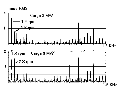
Note the relative size of the components at one and twice the rotational speed in the top and bottom spectrums and compare with the spectrum in Fig. 5.
In the upper spectrum, there are no symptoms of misalignment, while in the lower spectrum this is already noticeable.. The coupling when transmitting 3 MW of power was flexible and absorbed existing misalignment; the same did not occur when transmitting 9 MW.
If you want to know more about the effect on gear misalignment vibrations click here.
In toothed couplings, when the condition of the teeth degrades, a vibration begins to appear at the gearing frequency. (number of coupling teeth times rotation speed). Thus, in this type of coupling, it is important to follow this frequency.
If you would like to know more about the effect on vibrations of toothed couplings, click here.
blade couplings
In this link you can see an example of the effects of a fault on a blade coupling.
Example – failure in Cardan
A drive unit of a cylinder "Yankee", comprising a gear unit driven by two (2) motors as illustrated in Figure 16, Predictive Maintenance is included in the program defined by the customer, It is subject to regular inspections vibrométricas.

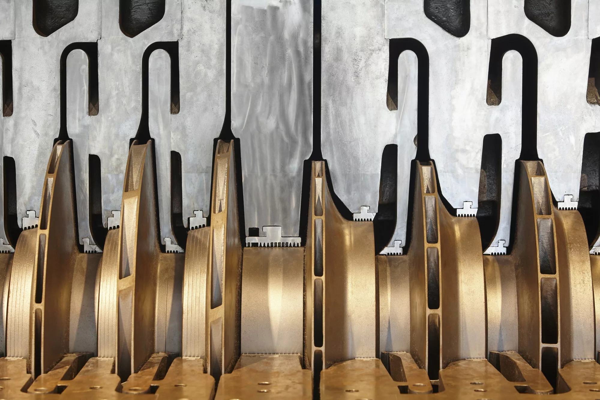
Figure 13 – Analysis of vibrations in gears – Photography of the drive unit
Inspection carried out in June, there was a significant increase in levels of vibrométricos presence in reducing, as can be seen in the trend graph shown in figure.
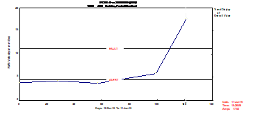
Figure 14 – Analysis of vibrations in gears – Trend Graph of the Overall Vibration Level recorded in the support of one of the input shafts of the reducer
The frequency analysis of the recorded spectra revealed that in the presence vibrométricos in reducing levels were, about everything, influenced by the amplitude of the second harmonic of the operating frequency of input shaft, as seen below .
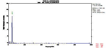
From this analysis, Also the fact that the protruding extent of operating frequency of the shaft gear unit input display greatly reduced amplitudes. For this facto, It was discarded as a cause misalignment first and foremost to the high levels recorded vibrométricos. That way, was recommended to the customer replacement / repair of unions "gimbal".
After replacement of joints "cardan", carried out by the technical services customer, during one of the scheduled installation stops, vibrométrica performed the inspection revealed a very significant reduction of the vibration levels is found that reducing subjected, as can be seen in the trend chart shown in Figure 19.
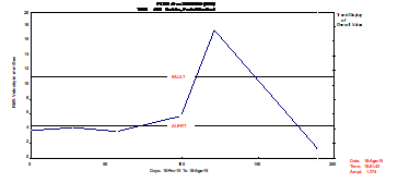
The decrease in severity originated vibrométrica, mainly, by decreasing the second harmonic of the operating frequency of the input shafts of the reducer, as can be seen in figure .

The inspection revealed the replaced components of accentuated degradation of the bearings and hangers, as can be seen in figure.

A iMPLEMENTING a Predictive Maintenance Program, based on the measurement and analysis of vibration, It allowed on time and without production losses, make it possible to intervene in the equipment minimizing intervention costs.
6 – Analysis of misalignment vibrations – Deformations and misalignment
6.1 – Hot misalignment
In machines operating at high temperatures there are always expansion phenomena that can lead to hot misalignment.. When this happens the cold machine does not vibrate, but when it heats up, high-amplitude vibration phenomena appear. Thus, in machines that operate at high temperatures, it is always necessary to check:
- – Existence of heating of the bearing support structures
- – Existence of cold compensation of hot deformations, if the bearing support structure is heated.
Symptoms of hot misalignment are the same as any other misalignment, being able, However, do some additional tests:
- – Monitoring of vibrations during the warm-up phase of the machine in order to determine if there is a proportionality between both parameters.
- – Temporary isolation of the heat source or cooling of the bearing support structure with monitoring of the evolution of vibrations.
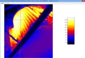
In the figure 13 you can see the evolution of vibrations, in the axial direction of a fan bearing, with hot misalignment, after insulating the support structure of a bearing from the heat source.
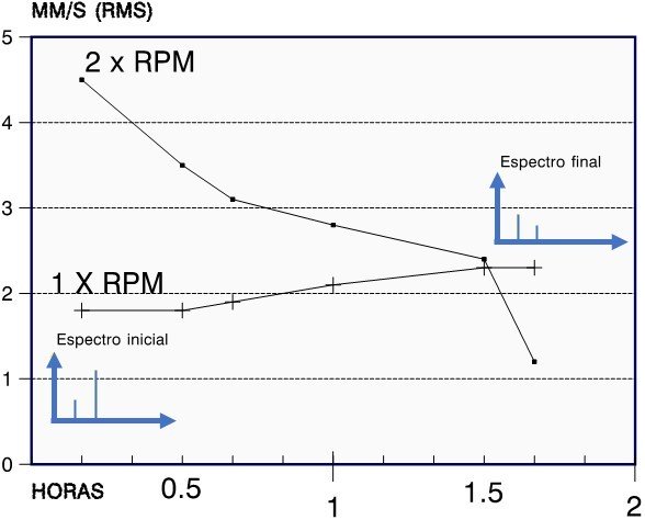
If you want to know more about the effect on vibrations of hot misalignment click here.
6.2 – Body Deformations
It is generally accepted that more than 40 % of electric motors show some form of deviation from the flatness of their bases.
On the other hand, it is rare for a machine base to be absolutely flat.
These factors lead to the tightening of the machine's fixing bolts sometimes leading to warping of its structure, causing misalignments.. The same can be said about connecting studs of pipe flanges.
The same can be said about connecting studs of pipe flanges..
The same can be said about connecting studs of pipe flanges.:
- – The same can be said about connecting studs of pipe flanges.
- – The same can be said about connecting studs of pipe flanges., The same can be said about connecting studs of pipe flanges.. The same can be said about connecting studs of pipe flanges. 0.05 The same can be said about connecting studs of pipe flanges..
- – The same can be said about connecting studs of pipe flanges., The same can be said about connecting studs of pipe flanges..
The same can be said about connecting studs of pipe flanges.:
- – The same can be said about connecting studs of pipe flanges.
- – I desaperto, The same can be said about connecting studs of pipe flanges., The same can be said about connecting studs of pipe flanges.. For this purpose, the vibration sensor is placed in the place where they are greatest and their evolution is observed as the legs are tightened and loosened..
- – Alignment with the machine in service, by observing the vibrations.
6.3 – Alignment with the machine in service
O alignment with machines in service It is a technique that has long been known and is often used by those who do not have other means or possibilities to do it. (Ex.: fishing vessels in emergency situations, submarines, where there is no access to equipment).
It is carried out as follows:
- – Place comparators on all shoes to track vertical movements (optional)
- – The machine to be moved is the one that is free (normally or electric motor)
- – Lighten the legs slightly (vibrations may rise slightly)
- – The motor at this point must move itself in the correct direction..
- – By attempts to find the best position.
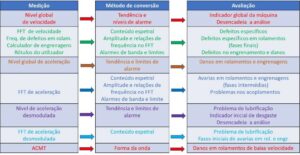
7 – Analysis of misalignment vibrations – Summary of trials and symptoms
The table below shows a summary of the tests to be carried out and the symptoms involved when dealing with misalignment situations..
| TechniquesSymptoms + misalignment vibration analysis figure | Global Level of Vibrations | strobe | Frequency Spectrum | Phase Measurement |
| vibration direction | X | X | ||
| Machine shape vibrate | X | X | X | X |
| Frequency of vibration | X | |||
| coupling state | X | X | ||
| phase of vibrations | X | X | X | |
| Base warp check | X | X | X | |
| load variation(in dentate couplings) | X | |||
| Temperature variation (on machines operating at high temperatures) | X | X | X | X |