Condition monitoring of seawater pump on ship
This article presents an example of seawater pump condition monitoring, on LNG vessel (Liquefied Natural Gas)
Introduction
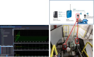
Artesis recently successfully completed a test installation of its Engine Condition Monitor (MCM) for the global shipping organization of a major GE customer – one of the largest energy companies in the world. The purpose of this installation was to validate the effectiveness of Artesis condition monitoring technology in various applications. This case history describes the results of the units e-MCM installed on two seawater pumps on board a Liquefied Natural Gas transport ship (LNG).
The customer's fleet
The shipping organization has more than 50 ships in its global fleet and is already well aware of the benefits of Condition Monitoring (CM), driving a successful global initiative to adopt fleet-wide CM technologies and programs. e-MCM offers the opportunity to monitor equipment that is currently outside of the existing CM program, where equipment may be inaccessible or in a dangerous location for workers.
For your wide range of ships, which include carriers of crude oil and products, transport oil tankers, Liquefied Petroleum Gas (GPL), LNG and hydrocarbon carriers, lube oil barges and offshore support vessels, the navigation organization applies a variety of tools to identify, prioritize, to assess, quantify, map and control risks – including the risk of asset failure and costly downtime.
Condition monitoring of seawater pump on ship – The project
The shipping organization's Engineering Superintendent was initially introduced to Artesis through an internal recommendation. Then, after reading articles in the engineering press and meeting the team at an industry event, became interested in exploring the capabilities of the e-MCM system on their own.
… OVER THE FOLLOWING MONTHS, THE ARTESIS TEAM PROVIDED EXCELLENT SUPPORT, ESPECIALLY DURING THE COMMISSIONING PHASE, WHERE VARIOUS SOFTWARE COMMUNICATION PROBLEMS WERE FOUND.
“As with all new technology on the market, There is a degree of skepticism when embarking on an early period of research and development,” stated. “To prove that the e-MCM unit could be a useful and valuable tool, we needed to determine whether it could accurately detect a failure before a catastrophic failure and, in the last instance, provide us with a non-intrusive monitoring process with cost-saving benefits.”
“After meeting with Artesis, we agreed that our validation testing would run to the point where a specific failure was predicted and maintenance was recommended, so that the forecast could be compared with the subsequent maintenance report. The units were then installed by the ship's energy specialist,” added. “The next few months, the Artesis team provided excellent support, especially during the commissioning phase, where several software communication problems were found.”
The machines
“The two engine-driven seawater pumps that were selected for monitoring are double-suction vertical centrifugal pumps in the main cooling system (Figure 1).”
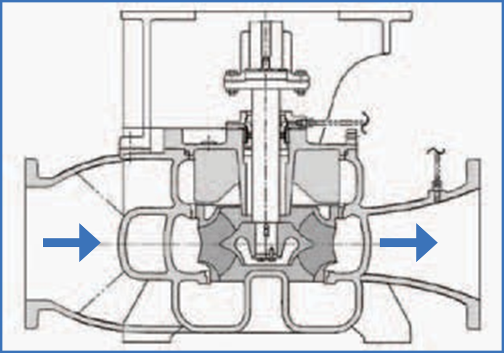
Figure 1: Cross-sectional view of the seawater pump, showing six-blade impeller with double wraparound suction. Directly coupled drive motor is not shown in this drawing.
Condition monitoring of seawater pump on ship – Machine condition assessment
Artesis carried out initial assessments with preliminary reports indicating that both monitored seawater pumps were experiencing chafing, misalignment, an anomaly in the blade passage and a reduction in pumping efficiency that suggested that initial misalignment had contributed to impeller damage.
Successive reports have increased indications of progressive erosion or corrosion of the pump's internal components, with a gradual decrease in energy consumption as the pump was able to do less useful work.
Monitoring experts predicted that pump performance would continue to decline as erosion progressed.. This analysis process also allowed the team to use power factor and electrical load (kW) as a simple indicator of pumping performance and the condition of erosion-prone parts.
Software information
The initial information presented by the software is in the form of “light signals” (red colors, yellow and green) in a diagnostic window (Figure 2).

Figure 2: This diagnostic window shows the situation that existed approximately 6 months after the start of the monitoring process, with level alarms 1 for Misalignment and Rotor Problems, as well as internal and external electrical faults that may indicate stator deterioration as a result of misalignment. Current imbalance alarms showed that it had increased to more than 10%, indicating possible stator damage.
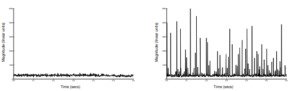
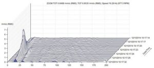
Red lights indicate a problem that requires attention, and simple guidance is provided regarding the urgency associated with the issue and the work required to resolve it. Additional information about these issues is available through trend lines that show how monitored parameters have changed over time (Figure 3).
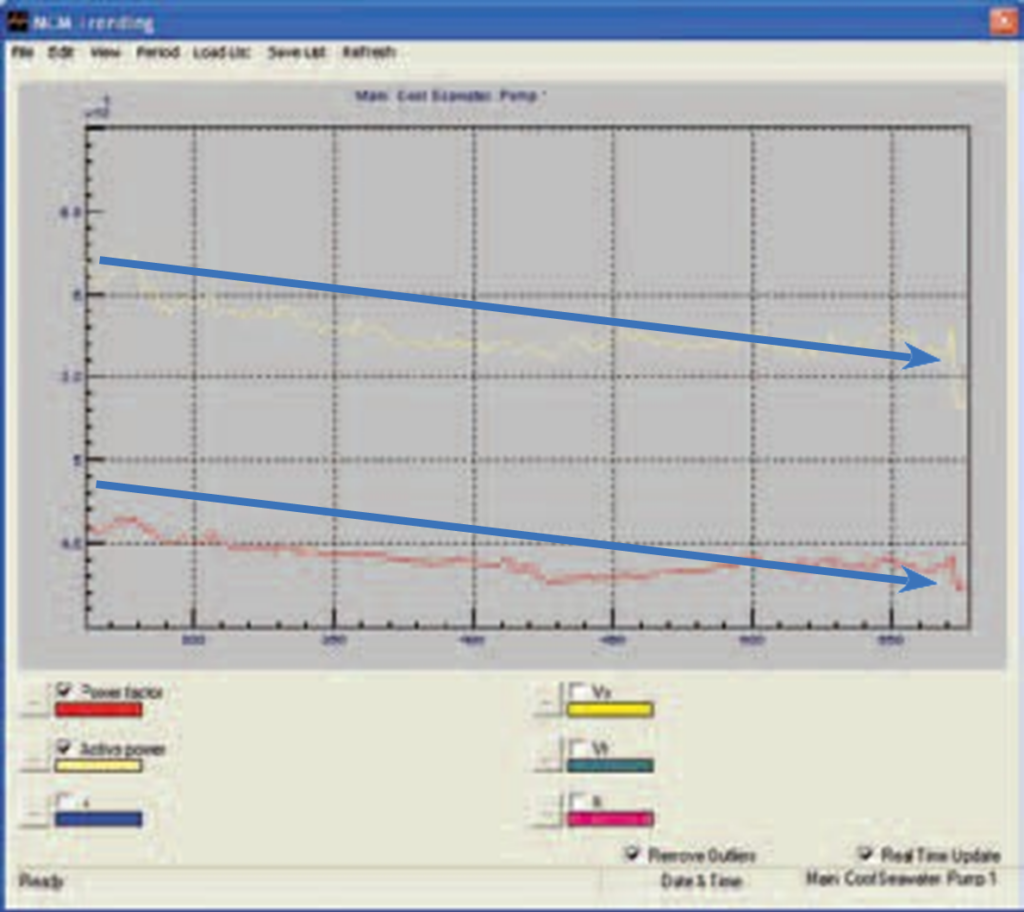
Figure 3: The trend graph shows a gradual progressive decrease in the active power and power factor parameters for the Main Cooling System Seawater Pump Number 1.
The trend curves
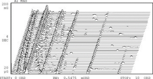
Trend curves can be displayed for all measured and derived parameters. In most cases, trend curves are automatically labeled with the parameter causing the anomaly. However, in some cases, an unusual problem may not be automatically classified by the equipment and requires expert interpretation. The specialist can analyze the power spectral density curve (PSD) and other parameters – which are beyond the scope of this article – to identify the nature of the underlying problem. In this case, it was possible to identify an anomaly corresponding to the blade passing frequency, confirming the diagnosis that something inside the pump was interfering with the normal, smooth flow of water.
Curiously, as time passed, power continued to decrease, but some indications of friction and engine stator problems have decreased, consistent with internal misalignment loads decreasing as internal wear occurred within the pump. This was followed by a decrease in the intensity of the blade passing frequency signals., indicating a loss of impeller effectiveness, suggesting it was heavily affected by erosion or other damage.
Condition monitoring of seawater pump on ship – The report made
By delivering a succinct and informative maintenance report at the end of the test, Artesis stated that there were signs of damage to the wear rings and a loss of performance consistent with a hole in the pump casing (Figure 4).
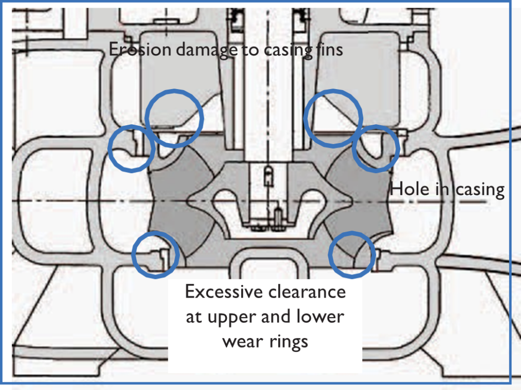
Figure 4: Identification of locations of degradation of pump conditions.
Condition monitoring of seawater pump on ship – inspection results
Once the power factor has fallen below a pre-determined limit, maintenance was scheduled to disassemble the engine and pump to compare the conditions found with the evaluations provided by the e-MCM unit. When the housing top cover has been removed, It was very evident that the flow blades (fins) had suffered significant metal loss due to erosion (Figure 5).

Figure 5: Pump internal parts after removal for inspection. Note significant metal loss at the ends of the casing flow blades (scrolls). About 19 mm of metal were lost in two locations. The thickness of the volutes was also reduced from the original dimension of 7 mm for 4,5 mm. It was discovered that the anomaly in the blade passage was caused by this damage, instead of impeller deterioration.
The impeller was slightly dirty, and the wear rings had eroded, causing a reduction in performance when allowing recirculation flow. A small hole had also been eroded into the pump casing., where a disturbance in flow was produced by a wear ring retaining screw (Figure 6).
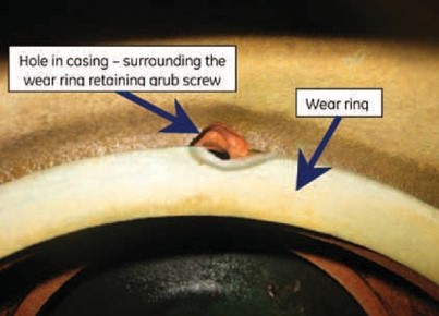
Figure 6: When disassembling, It was discovered that erosion had formed a hole in the pump casing, at the point where a wear ring retaining screw has caused a localized disturbance in the flow.
Condition monitoring of seawater pump on ship – pump intervention
• The impeller was in good condition, then it was simply cleaned and reused (Figures 7 e 8).
• Eroded wear rings have been replaced, restoring normal clearances and pump efficiency.
• Hole in pump casing was repaired using cold resin techniques, preventing further deterioration of the carcass in that location.
• Although the carcass fins were heavily eroded, they were not significantly impacting performance, so the housing cover was reused without repairing the fins.
• The cost of repairs was approximately 10% of the cost “normal” pump replacement associated with the previous Run to Fail regime (OTF).
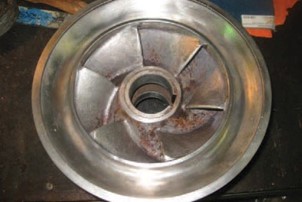
Figure 7: Impeller after cleaning. Axial view of one of the impeller eyes (suction).

Figure 8: Impeller after cleaning. Radial view of the impeller blade tips (discharge).
Subsequent replacement of the wear rings and repair of the hole in the casing helped restore pump efficiency to normal levels. It was also reported that the repair of the hole in the casing, where is the wear ring retaining screw located, saved the pump casing from further deterioration. Although the pump casing fins suffered significant material loss during testing, and has been advised that these should be repaired, this was not essential to the operation of the pump. No damage to the rotor or stator of the drive motor was recorded., and no harm was suggested by the test data.
Condition monitoring of seawater pump on ship – the completion of the test
Upon successful completion of the test, the Engineering Superintendent concluded: “Online system monitoring was the most beneficial part of the testing process. Use a simple traffic light system to identify the existence of a fault, when and where appropriate, allowed intrusive investigations and repairs before failure. This online remote indication enabled a reduction in maintenance man hours and downtime. e-MCM units have the potential to save on replacement parts, and we continue to evaluate Artesis functionality in various applications within our fleet.”

The application of e-MCM technology has facilitated the implementation of a proactive approach to pump maintenance, resulting in a reduction in production costs 90% compared to the previous method of replacing the entire pump after its failure.