Fault finding in bearings running at very low rotation speed, with acoustic emission
Victor Duarte, DMC Engineering and Iberian Systems
resume
Acoustic emissions are a facet of vibration, at much higher frequencies than those monitored by traditional vibration measurement techniques; frequencies far above 20 KHz. This technique seeks high frequency signals of cracks or impacts, instead of repetitive synchronous movement of vibration. It is a purely passive technique, unlike ultrasonic inspection, in which the ultrasound is transmitted and detected through objects.
Acoustic emission measuring equipment, for bearing failure detection, have particular application in the monitoring of machines that rotate at speeds between 0,25 rpm e 60 rpm. Malfunctions in the bearings of low speed machines are traditionally very difficult to monitor with traditional vibration techniques. With the measurement of the acoustic emission these faults are very simple to detect.
This article presents the principles of technique and practical cases of application.
To view a presentation on this topic click here.
1. Introduction
The purpose of monitoring the operating condition is the detection and identification of faults at an early stage of its development so that, timely, You can set and take the appropriate measures and decisions, which minimize the occurrence of unintended stop with the consequent costs associated. since mode, the condition monitoring techniques must be sufficiently sensitive to detect faults in advance. Even more, these techniques should be applied in various types of machines, It is quick and easy to use, and having a high success rate in the detection and identification of faults (minimizing the number of false alarms).
It easily follows that there is provided control technique that alone, meets all these requirements.
The application of traditional vibration measurement and analysis techniques for bearing failure detection becomes progressively more difficult, as the engine rotation speed is lower.
The application of acoustic emission measurement in bearings aims to complement other condition control techniques, where they have less potential.
2. The machines run at very low rotational speeds
industry, the machines run at very low speed are often critical to the production process and, simultaneously, large, This means that processes such as generating mechanisms of friction and impacts present, normally, a low ratio between the generated signal and the background noise.
It is this type of applications that the Emissions Measurement Acoustics (AE) and including measuring acoustic emission bearing, becomes important, by allowing in a simple way, but effective, detection of the activity produced by degradation mechanisms of a bearing even at low rotational speeds.
3. The limitations of bearing vibration analysis techniques
It is known that the application of traditional measurement techniques and analysis of vibrations becomes progressively more difficult, as the engine rotation speed is lower. The reasons for this are:
- The release rate of energy produced by a low defect as lowering the rpm's;
- The defects of the repetition frequencies become too low and difficult to identify against the background noise present.
These difficulties, cause the search for new condition control techniques, so that it can address the monitoring of bearing condition to operate at low rpm's in a more effective way, leads to the development of techniques such as the measurement of Acoustic Emissions (AE), and including measuring acoustic emission bearing.
4. The acoustic emission
Acoustic Emission technology is a non-destructive test method, used in a wide range of industrial applications to detect and locate defects in mechanically loaded samples. The acoustic emission was formally defined as “the class of phenomena in which transient elastic waves are generated by the rapid release of energy from localized sources within a material, or transient elastic waves thus generated”[1]. such waves, usually, take the form of high level of tension band waves and broad frequency that, to be measured, They are received and converted into electrical signals by piezoelectric transducers.
The configuration and the hardware of acoustic measurement systems, in particular for measuring acoustic emission bearing, may vary by application, It is required four common components for acoustic measurement data:
- a source;
- A framework through which the source can propagate;
- O sensor (transducer);
- And the electronics to record and process data.
5. The variation of the acoustic emission with the rotation speed
All machines in operation, have associated frictional energy losses and this results in voltage waves generated that can be detected by surface-mounted acoustic emission sensors. Although there are exceptions, it is common for those with a high signal to noise ratio, It is generated, mainly, friction and contact surfaces. Other source processes often found include crushing debris, turbulence and cavitation. The speeds of the machines contact surfaces, result in higher energy release rates, and produce higher levels of continuous signals (such continuous signals resulting from the superposition of many small transient signals). To illustrate this, the average magnitude of the signal detected from a lubricated roller bearing, in good conditions, at various speeds of rotation, It is shown in Figure 1.
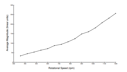
Figure 1 - acoustic emission measurement in bearings – Effect rotation speed of the signal generating continuous acoustic emission level [2]
This relationship is typically found for acoustic emission measurements, in most rotating machines. However, any bearing, the signal levels detected at any specific rate, also depend on the type and bearing size, the applied load, the lubrication efficiency and the presence of damage.
6. The characteristics of acoustic emission signal
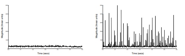
In the continuous component, the detected signal can display discrete signal tours, each corresponding to the occurrence of the most significant sources of transient, which may be indicative of damage.
For example, the figures 2 (a) e 2 (b) show signal waveforms to dynamically equivalent envelope, a roller bearing, with and without an introduced defect (defect caused by electrical discharge that corrodes a line on the inner track). The transient clearly visible in Figure 2 (b) result from impacts with individual rolling elements, passing over the track corrosion line. The high sensitivity of acoustic emission sensors to such transient, It provides the basis for the direct detection of damage related signs at an early stage, analyzing the signals in the time domain.
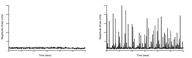
| Figure 2(a) Dynamic envelope signal of a roller bearing in good condition. [2] | Figure 2 (b) – Dynamic envelope signal of a roller bearing defect with the inner race. [2] |
Observe also how the acoustic emission measurement signal bearing in Figure 2 (b), It has time intervals where transients are repeated, but that there is significant variation in amplitude away with some of the expected transient. This probably corresponds to the relative position of the defect in relation to the zone charged at the exact moment that a roll with it impacts. Such variations of amplitude and time could be used to reveal more about the nature of the defect. However, on the occasions when such diagnostic information about the failure is needed, it is more usual time transform signal in the frequency domain to observe defects repetition frequencies in a similar manner to the envelope based on vibration analysis. For such analysis, it is clearly necessary to have detailed knowledge of the geometry of the machine or rolling, and accurate speed information.
7. The measurement of acoustic emission at very low speed
Another consequence of the dependence of signal level detected speed (as illustrated in Figure 1), is that, as the surface speed continues to decrease, the continuous signal level of the detected acoustic emission measurement bearings, eventually, falls below the measurement limit of detection system. Sometimes, this occurs when monitor very low surface speeds. Although this may seem like a limitation to the application of acoustic emission measurement method bearings engines at low rotational speeds, experience suggests that, even when there is no discernible level of continuous signal, The presence of detectable damage is still detectable by the occurrence of transient signals (be subjected to an appropriate sound path between the source and the sensor). The success of the acoustic emission measurement in such applications is especially important, since the human senses become ineffective at very low speeds and vibrations monotorização becomes especially difficult, if not impossible to apply.
8. Practical case of application of acoustic emission measurement in bearings in a press
In pulp washing press, bearings which operate at about 10 RPM, It has implemented an inspection plan for the four condition monitoring (4) installed bearings, by measuring acoustic emission bearing, At a frequency of measurement bimonthly.
8.1 Results of routine measurements
The inspection results measured with acoustic emission bearing, over a period of about 2 years, revealed amplitudes Distress parameter® lower than the set alarm limit for the bearing in question, as can be seen in the graph shown in Figure 3.
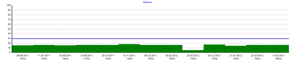
Figure 3 - acoustic emission measurement in bearings – Distress amplitude values of the parameter® Registered in the bearing #3 along the inspections carried out for about 2 years [3]
The next inspection by acoustic emission measurement bearings, after about 2 months, was recorded in the rolling #3 a significant increase of the amplitude of said parameter. In that inspection, the amplitude value of the recorded acoustic emission bearing measurement was higher than the set alarm limit for the bearing in question, as can be seen in the graph shown in Figure 4.
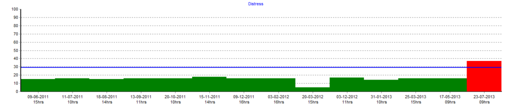
Figure 4 - acoustic emission measurement in bearings – Distress amplitude values of the parameter® Registered in the bearing #3, revealing a significant increase [3]
8.2 recommendation made
After new measurement of acoustic emission measurement in bearings, for confirmation of the registered change, the Technical Services was informed of the recommendation for a maintenance intervention, in order to carry out the replacement bearing #3. Since this intervention required a high of machine downtime, replacing the bearings it was planned to effect a programmed stop during the installation with a duration of 48 hours. Until the completion of said stop, the period between inspections of measurement of acoustic emission in bearings has been reduced and the results obtained are presented in the graph of Figure 5.
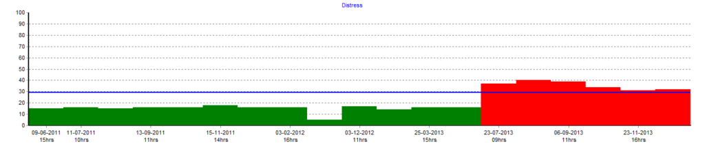
Figure 5 - acoustic emission measurement in bearings – amplitude values of the parameter Distress® Registered in the bearing #3 during the period in which it was under surveillance [3]
Note also that other parameters recorded during inspections, more specifically, the value of the peak signal amplitude of AE, He showed the same characteristic parameter observed in Distress® (Figure 6). The behavior observed through the evolution of this parameter is an indicator of the presence of a significant single event that causes the abnormality detected in the bearing.
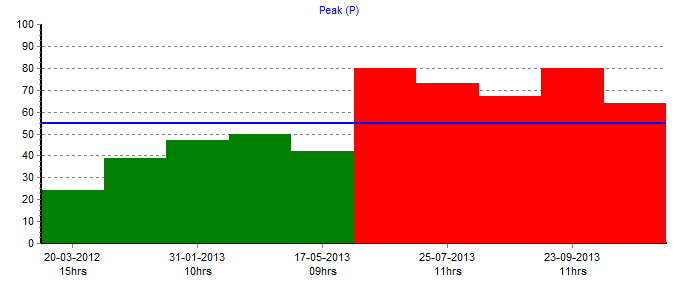
Figure 6 - acoustic emission measurement in bearings – Amplitude values of the AE signal peak parameter registered in the bearing #3. [3]
8.3 State it was in the bearing
The Technical Services carried out the intervention, as it had been programmed, and Figure 7 It shows the replaced photograph bearing. As can be seen, the bearing inner ring #3 It is found fractured.
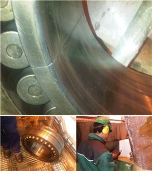
Figure 7 - acoustic emission measurement in bearings – Rolling with fractured track
8.4 Measurements after repair
After replacement bearing a new acoustic emission measurement was conducted bearing inspection, in which a significant decrease of the amplitudes of the parameters for monitoring the condition, as can be seen in the graphs of Figure 8 Figure is yes 9.
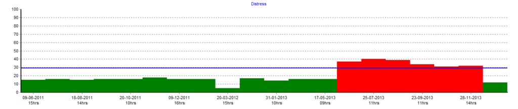
Figure 8 - acoustic emission measurement in bearings – Distress amplitude values of the parameter® recorded after the replacement bearing #3 [3]
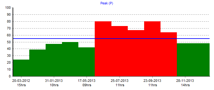
Figure 9 - acoustic emission measurement in bearings – AE signal peak amplitude parameter values recorded after replacing [3]
9. Conclusion
The implementation of an inspection plan based on the measurement of acoustic emission in bearings made it possible to identify the development of a potentially catastrophic failure, on a bearing running at 10 RPM.
In an application wherein the vibration measurement and analysis had shown not to be the condition monitoring technique, suitable for monitoring the condition of bearings due to machine characteristics, in particular, the implementation of a plan of inspections based on acoustic emission measurement bearings, It demonstrated that it is possible to overcome the technical difficulties that other technologies have, when it is desired to monitor the operating condition of bearings to operate at very low rpm's.
References
- ASTM E1316-06A Section B: Acoustic Emission
- THE APPLICATION OF AE IN CONDITION MONITORING, Trevor J. Holroyd, Holroyd Instruments Ltd.
- Customer report, Victor Duarte, DMC