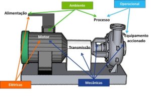
Permanent vibration monitoring systems
1 – Permanent vibration monitoring systems
Permanent vibration monitoring systems, as the name suggests, are permanently installed in a machine and continuously monitor its operating condition.. Permanent vibration monitoring is mainly employed to give immediate warning of sudden changes in the condition of machines., high value, and not duplicates, whose service is fundamental to the production process. A fault condition is detected immediately or shortly after its occurrence., stop relays or alarms can be triggered in the control room to take appropriate action before a catastrophic failure occurs. These systems are widely used, long ago, in electric power plants and in the petrochemical industry in turbines, generators, compressors, etc.
This article belongs to a series, which constitutes the support material for the course on vibration analysis in turbomachinery. Links to the other articles can be found on here.
2- Approaches to vibration monitoring
There are basically two types of vibration monitoring equipment.:
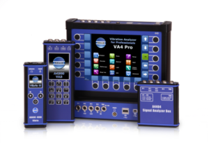
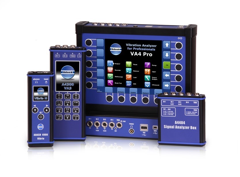
– Laptops - offline (meters and Vibration analyzers )
– Permanentes – on line
Monitoring equipment permanently installed in a machine can monitor it in two ways.:
– Periodically
– permanently
It is usually defined as permanent monitoring that occurs at intervals less than 0,1 seconds.
The monitored parameters can be of two types.:
– Scalars
Parameters defined by a single number (Ex.: Temperature)
– Matrices
Parameter defined by a set of numbers (Ex.: Spectrum Frequency)
The generated alarms can be of two types.:
– Of level
– of trend
Alarms can also have different purposes.:
– Alert
– Danger
– machine stop – this function is only used in permanent monitoring systems..
Monitoring itself can have two different goals:
- protective monitoring
- predictive monitoring
3 – protective systems
As for its working principle, two types of protective systems can be distinguished:
– Simple Mechanical Devices
– Vibration amplitude monitoring systems
3.1 – Simple Mechanical Devices
This type of device, that historically were the first to appear, , relies on a simple mechanical effect to trigger a relay when the amplitude of vibrations exceeds a certain level. There are devices of this type based on magnets, in mercury balls in cup, etc.

3.2 – Vibration amplitude monitoring systems
In this type of systems there is always one or more vibration sensors connected to measuring equipment and that, in case a predetermined level is exceeded, trigger a device to stop an installation through a relay.
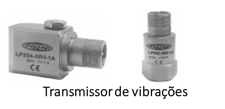
3.2.1 O vibration transmitter
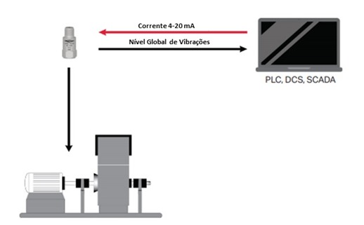
The simplest and consequently the most economical system of this type, is based on vibration transmitters.
A vibration transmitter is a sensor with an output of 4-20 mA and that, therefore, can be connected directly to a PLC or a traditional data acquisition unit. This PLC can command the machine stop and/or perform data acquisition in order to be able to perform trend analysis.
The great advantage of this type of sensor is that it does not need a dedicated measuring unit, which is traditionally used when sensors have an output in Volts. The system as a whole is therefore simpler, resulting in reduced costs.
When the purpose of the online system is just to protect, by following a global level this is the most logical solution.
3.2.2 Dedicated systems with sensors with outputs in Volts
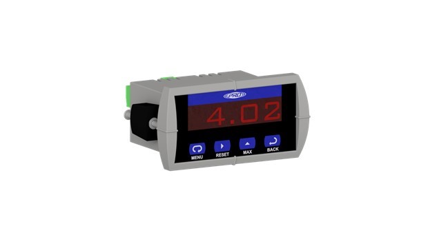
These devices are usually connected to piezoelectric accelerometers. In a basic system, a single module can continuously control vibration over a single specific frequency range.. If predefined limits are turned on (for example, Minimum, Alert and Alarm) the system can trigger visual or audible alarms.
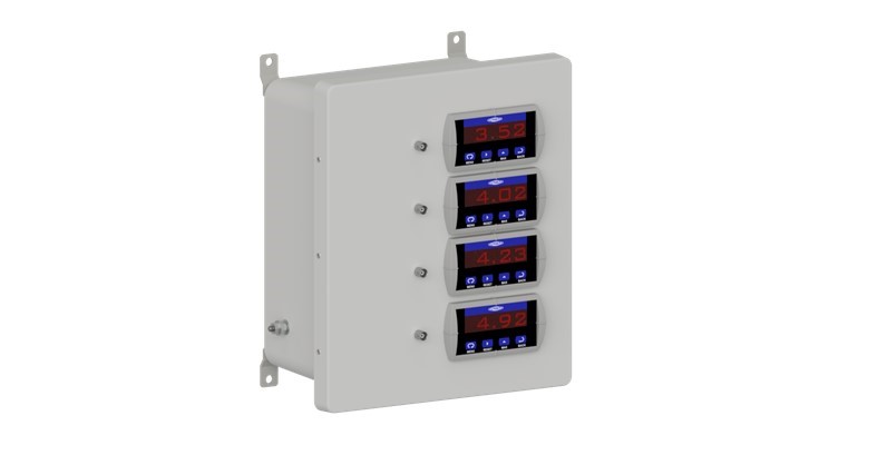 |  |
Systems of this type may have one or more channels.
A unit typically has the following functions:
• Two configurable alarm levels with timing with relay activation
• Exit 4-20 mA for connection to PLC
• Volt output for connection to vibration analyzer
• Vibration sensor power supply (accelerometer ICP, proximitor, etc.)
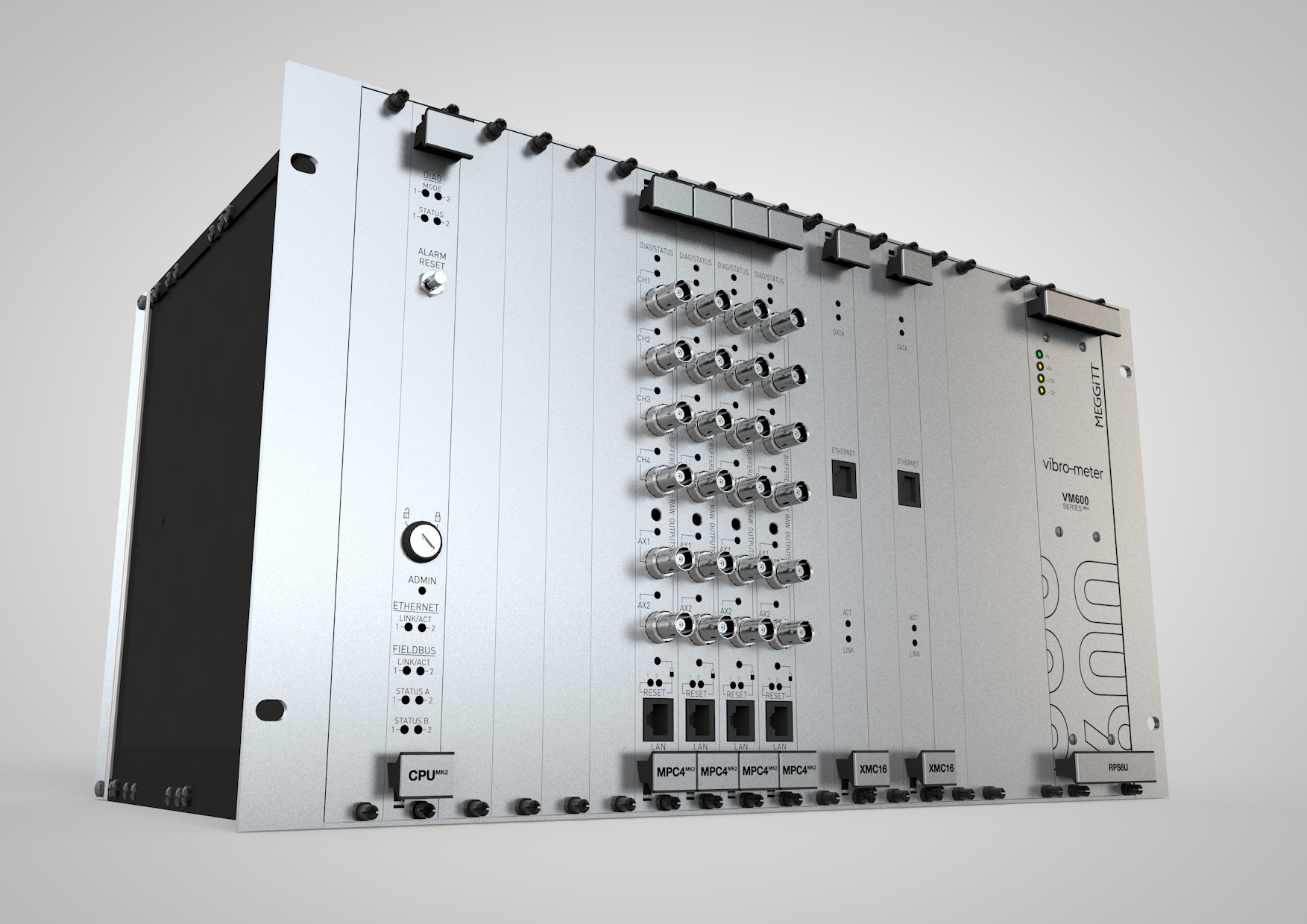
Below you can see a vibration monitor meeting the requirements of the standard API 670 (API Standard 670 – Machinery Protection Systems)

4 – Permanent predictive vibration monitoring systems
meters and, meters and vibration analysis, meters and predictive maintenance, meters and, for critical machines, also permanently installed predictive systems.
predictive systems, nowadays, always include a computer for post-processing the measurement results..
4.1 Off line systems – O vibration analyzer and data collector
Any measurement equipment can be the basis of an offline predictive system being the most common example, in the process industry, the data collector.
There are numerous variants of this type of systems., but with regard to vibrations, the main conditions are as follows:
• Whether or not they have memory and be associated with a computer program (for loading and unloading inspection routes and presenting measurement results thus eliminating the most significant part of bureaucratic work).
• Have the ability to perform frequency spectrum analysis (on the equipment or on a computer to be able to perform a diagnosis)
• Be more or less quick to take measurements (very important when they are intensively used).
4.2 Permanent vibration monitoring systems
There is a wide variety of predictive systems online. Traditionally they were high cost solutions in which there was always the ability to perform spectrum analysis. however nowadays, there are also, low cost solutions.
4.2.1 Permanent vibration monitoring systems based on vibration transmitters with output 4-20 ma
these systems, having as acquisition unit a PLC or a traditional unit, present as their main limitation the fact that it is not possible to carry out a spectrum analysis and, therefore, are very limited in terms of diagnosis..
However, it is also true that, oftentimes, the malfunctions are repetitive and easy to diagnose.
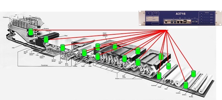
4.2.2 Multiplexed permanent predictive vibration monitoring systems
Multiplexed predictive systems have multiple acquisition channels for each measurement channel. They are used in machines whose breakdowns have a slow evolution.
Examples of this type of system are those normally used in paper machines where speed of measurement is not an essential feature.
4.2.3 Permanent vibration monitoring systems – integration of protective and predictive systems
Protective systems, most recent, often have the ability to send data to a computer, which is then analyzed, thus constituting a predictive system.
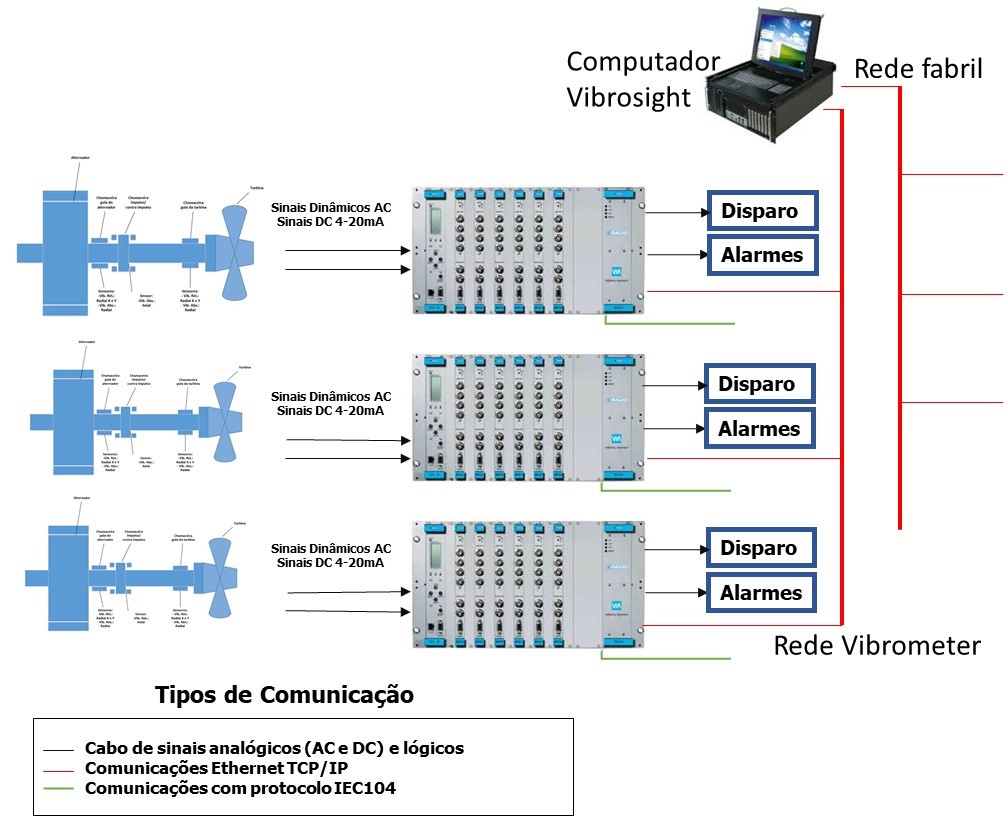
Since always, predictive permanent monitoring systems, for turbo machines constitute the most sophisticated systems of all. This fact stems from the rapid variations in speed that these machines are subject to., disallow the use of slow systems, multiplexados, e, therefore, each sensor has to correspond to a measurement channel.
Furthermore, the detection of some types of failures associated with these machines leads to the need to monitor transient phenomena, associated with starts and stops and the implementation of sophisticated real-time signal analysis techniques (ex.: order follow-up).
It is also a common requirement for this type of systems to be connected, networked, to process control systems making the set quite complex and sophisticated.
In this type of systems it is common that the protective and predictive functions are separated to ensure the minimum reliability adequate for this function., in accordance with the requirements of the API670 standard.
4.1.2 Permanent wireless vibration monitoring systems
The essential features of this type of systems, to be designated as a wireless system, are:
• Sensors are battery powered (do not need power cords)
• The sensors are connected to the data collection unit via a wireless network (do not need signal transmission cables)
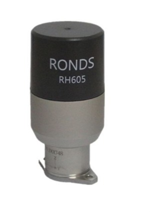
The widespread use of computer technologies in instrumentation has led to the emergence of permanent wireless vibration monitoring systems, as shown in Figure.
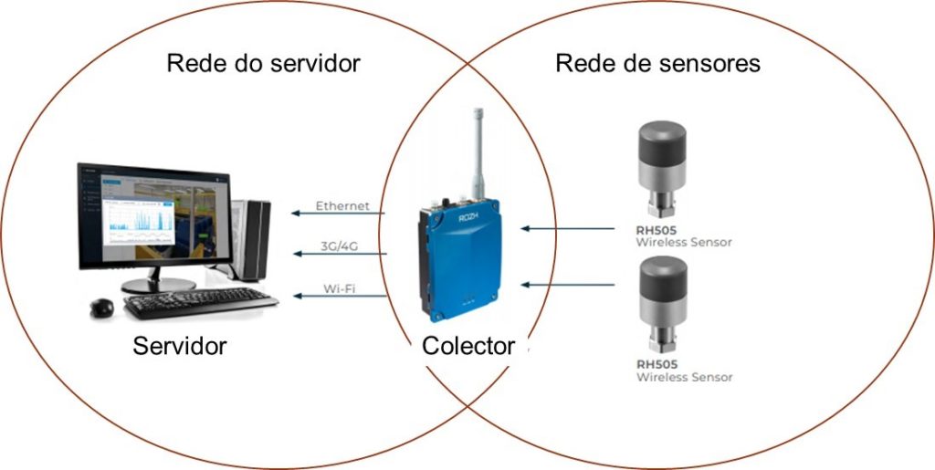
to today (2021), in this type of systems, the communication between the collector and the sensors is intermittent and, therefore, these systems do not have protective functions.
Features of wireless sensors
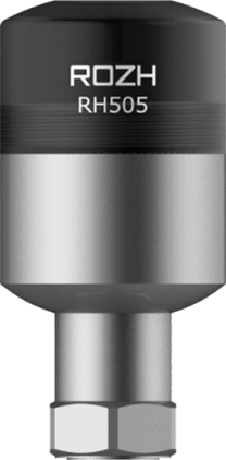 |  |
In addition to the aforementioned characteristics, it is convenient for the sensors to have the following characteristics:
• Be able to measure simultaneously in displacement, velocity and acceleration, waveforms and spectra;
• Be able to simultaneously measure temperature;
• Uni or triaxial models are available;
• Global levels can be measured in RMS or Peak values;
• The number of measurement lines can be defined by the user;
• Sensors can trigger additional measurements based on user-defined values;
• The measurements of the different sensors are synchronized between them;
• Sensors have memory.
• IP67 minimum;
• Explosion-proof (Ex.: Exia ⅡCT4);
• Fault notice (Watchdog)
Since the sensors are battery powered, it is convenient to have the following characteristics:
• May have different measurement periods, for measurements of global values and spectra or waveforms;
• Values can be defined below which the machine is considered to be stopped and the more complex measurements are not taken;
• The sensor battery can be supplied and mounted locally.
Characteristics of collectors of wireless vibration monitoring systems
It is convenient for these units to have the following characteristics.
• Communication: 4G or Wifi or Ethernet;
• Local memory;
• Anti-explosion design;
• Fault notice (Watchdog)
• IP66 minimum;
General characteristics of wireless vibration monitoring systems
It is convenient that the systems also have the following characteristics:
• Interface com mimico;
• Web interface, App and server;
• Alarm alerts by SMS and e-mail;
• Support industrial communication protocols. OPC, Modbus, API
• Multiple diagnostic graphics options: single and multiple trend, spectrum and simple waveform, multiple and spectral map, etc.
5 Examples of selection of vibration monitoring system
5.1 general approach
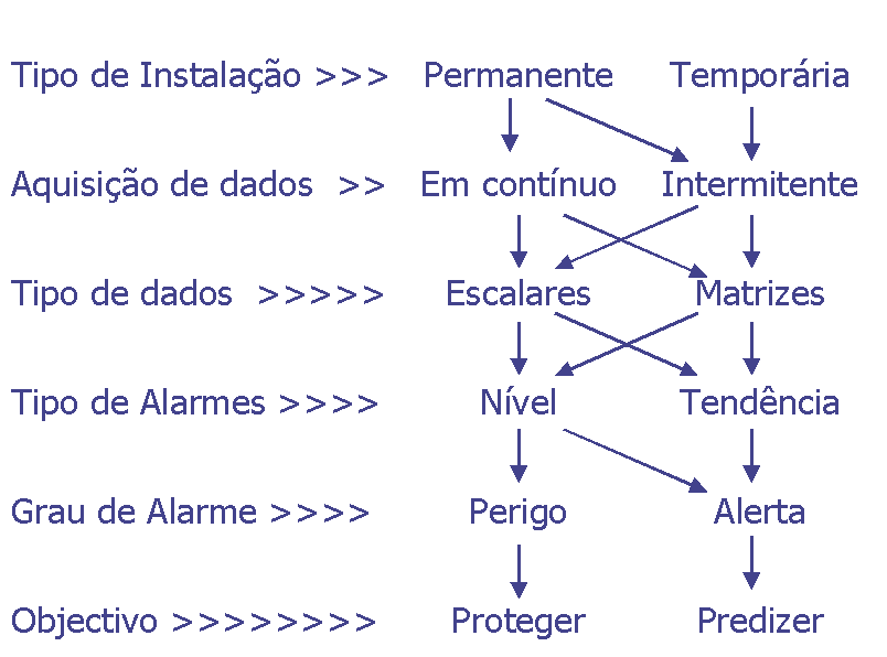
The sequence of decisions that lead to the choice of a measurement equipment or system is shown in the figure, then presented.
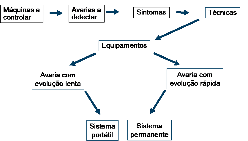
The first step is to define which machines will be controlled. This choice is made according to technical-economic criteria. Usually the choice falls on equipment whose failure has a strong economic impact or is relevant for safety. Another factor that usually also weighs on the choice is the feasibility of the control to be carried out.
Selected the equipment that will be controlled, the faults to be detected are listed. The most common malfunctions are necessarily included. More rare malfunctions may or may not be, according to the importance of the machine, consequences of the breakdown and additional costs for its control.
To monitor malfunctions, we try to detect their symptoms. Each malfunction may have one or more symptoms. The choice of symptom to control depends on several factors.. Normally, one tries to monitor symptoms common to the various malfunctions, in order to minimize the number of detection techniques to be implemented.
Another very important parameter influencing the choice is the purpose of surveillance.
Surveillance of a machine can have two distinct purposes.: can serve to protect her and/or to predict her future behavior.. This choice has relevant consequences., especially when it comes to monitoring malfunctions that evolve quickly, where a permanent system may be required.
The techniques to implement depend on the symptoms you have chosen to control. Normally, we seek to select the techniques that detect the greatest number of symptoms, with adequate sensitivity.
Having made the foregoing choices, you are in a position to draw up the technical specification of the equipment or control systems. At this stage in addition to the aforementioned aspects, may weigh others related to computerization, organization, etc.
5.2 Example 1: centrifugal bomb
Let's consider the case of a very common machine; a centrifugal pump, with about 30 KW e a rodar a 1500 rpm, for example. The most common malfunctions are shown in the figure..
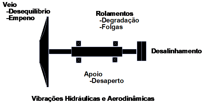
In the table below, the most common malfunctions and their symptoms are seen..
| Symptom breakdown | Temperature | Pressure | Caudal | Vibration |
| Imbalance | X | |||
| Misalignment, Warped came | X | X | ||
| bearings | X | X | ||
| Awakenings, Days off | X |
It becomes evident here that the singular parameter where most symptoms of failures are manifested is vibration. This is the most suitable parameter to follow.
To choose the detection techniques, it is necessary to take into account the way in which the vibrations arise.. In the frame you can see its characteristics..
| Defect | Frequency | Amplitude |
| Imbalance | 1 X RPM | Elevated |
| Misalignment Warped came | 1,2,3 X RPM | Elevated |
| bearings | High Frequencies (Bigger than 1 KHz) | very small, at the beginning |
| Awakenings Days off | 1 X RPM n X RPM | Elevated |
This bomb being relatively small, the ultimate goal of control is to predict your future behavior, in order to support Maintenance Management decisions. On the other hand, the faults in question have a slow evolution, Easy to follow.
The application of portable equipment, to allow for regular measurements should, therefore, provide satisfactory results.
The measuring equipment must therefore be portable and be able to measure the amplitude of vibrations at the speed of rotation and its harmonics to detect imbalances, desalinhamentos, warped veins, looseness and looseness, and simultaneously, measure the amplitudes of vibrations at frequencies greater than 1 KHz to detect early signs of bearing degradation.
The first ones must be done in Effective Speed to be easily comparable with the most disseminated Norms and the second in Acceleration for greater sensitivity of the technique.
In addition to what has already been mentioned, it is now necessary to define some parameters that do not directly have to do with the detection of failures in pumps, are also relevant. These are the requirements in terms of diagnostic and computerization capabilities of the measurement system.
5.3 Example 2: Process Turbo Compressor
Now consider a process gas compressor in a petrochemical, multi-stage compression. Typically, will be a machine with anti-friction metal bearings, running at high speed, powered by a steam turbine or an electric motor. The power of the drive will be, for example, of 2 MW.
The figure below shows typical failures and their evolution speed.
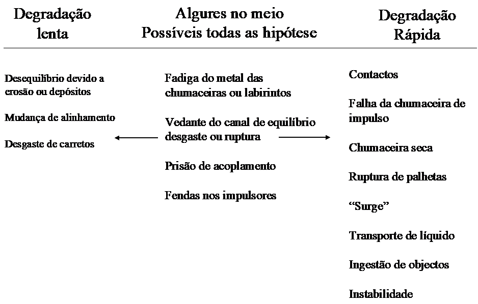
Most of these malfunctions have multiple symptoms. Thus, taking into account the importance that this machine assumes in the production cycle and the maintenance costs involved, the following symptoms are monitored.:
- Radial Vibrations
- Axial position of the shaft
- Bearing temperature
- Pressures, Temperatures, Caudais
- velocity
The economic consequences of an unexpected breakdown and the speed of evolution of many of them mean that the machine is permanently protected. Thus, the sensors for measuring the aforementioned quantities are permanently mounted and automatically trigger alerts and stop relays when the measured values exceed pre-defined values.
Thus, the instrumentation to be installed in the compressor would be the one shown in the figure.
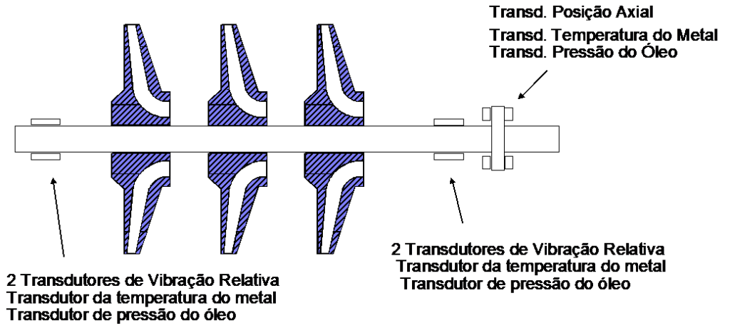
This way the machine is protected from damage caused by unexpected malfunctions.. However, for the good technical-economic management of this type of machinery, it is essential that there is reliable information, readily available, easy to understand, about what happened or is going on, so that you can predict your future behavior and make the most appropriate decisions.
For this purpose the protective system described above does not provide sufficient information; it is necessary that the measurement results of the various sensors are acquired by a computer and properly treated and presented.
The functions to be performed by this system are:
- Data acquisition
- Data compression
- Automatic Alert Generation
- Implementation of Diagnostic Techniques
- Day to day
- Start and Stop
The measured values will be acquired by a computer that will provide the following information:
- visualization
Multiple parameters over time
Frequency Spectra
Position of Grounds
Bodé
Polar diagram
Spectral Map
Analysis by Orders
Vector
Orbit
Any parameter depending on another - Automatic Alarms
For each machine state:
In service, load dependent
Stopping and Starting
in slow rotation - User-defined format reports
When there are occurrences, according to user-defined criteria, the acquisition of each parameter must be performed with intervals of a few seconds in order to be able to, later, understand the fastest transient phenomena. Consequently, it is also necessary that the system has a data compression system in order not to overload the computer disk with useless data.