Vibrations in oil film bearings
A Vibration Analysis in oil film bearings, has particularities that are very important. This analysis is often carried out with a vibration analyzer and/or vibration monitors.
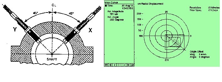
In turbomachinery this type of bearings are normally instrumented with displacement sensors (proximitors).
De facto, with proximitors, degradation of oil film bearings, or malfunction, can be better monitored and inserted in a program of Predictive maintenance.
This article belongs to a series, which constitutes the support material for the course on vibration analysis in turbomachinery. Links to the other articles can be found on here.
1 – Oil film bearings
1.1 Operating principle of oil film bearings
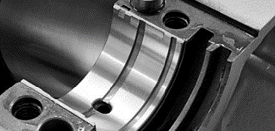
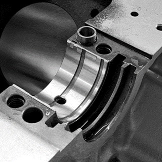
In an oil film bearing, the stationary surfaces (bearing bush, or similar) and rotary (shaft mill) are separated by a thin film of lubricant, are separated by a thin film of lubricant, With, are separated by a thin film of lubricant.
are separated by a thin film of lubricant, are separated by a thin film of lubricant (are separated by a thin film of lubricant) are separated by a thin film of lubricant.
are separated by a thin film of lubricant.
1.2 are separated by a thin film of lubricant
are separated by a thin film of lubricant, the converging geometry is provided by the small difference in shaft spool and bearing bush diameters.
To improve static and dynamic performance, set can be designed or machined in the bushing, a profile to develop the appropriate film.
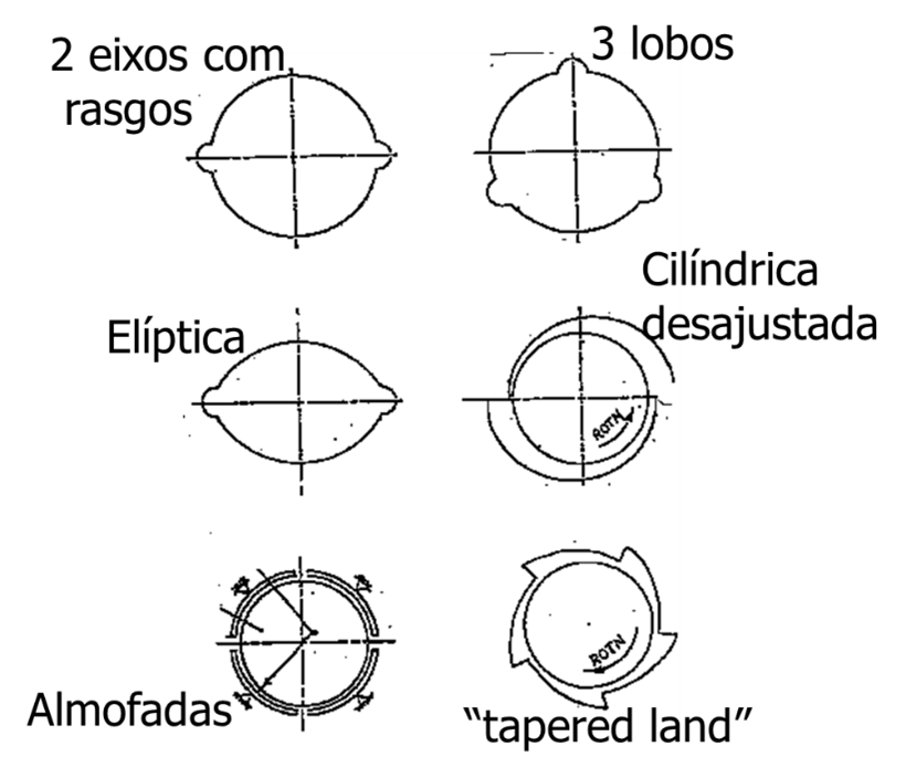
In axial thrust bearings, converging geometry is machined into the face of a fixed plate or provided by the tilting action of the pads.
A fixed geometry is designed for a specific condition, so that the angled cushion bearings (tilting pad) are often used to accommodate changing conditions..
1.3 are often used to accommodate changing conditions.
are often used to accommodate changing conditions., are often used to accommodate changing conditions..
are often used to accommodate changing conditions. (are often used to accommodate changing conditions.). are often used to accommodate changing conditions. (are often used to accommodate changing conditions.).
are often used to accommodate changing conditions..
1.4 are often used to accommodate changing conditions.. are often used to accommodate changing conditions.
A key difference between bearing and oil film bearings is the expected life.. Bearing bearings typically have a predictable life based on operating conditions. (a calculated service life L10). Oil film bearings, when properly designed and maintained, can operate for decades.
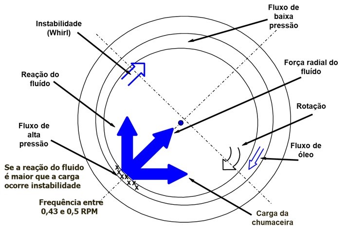
1.5 Instability in oil film bearings
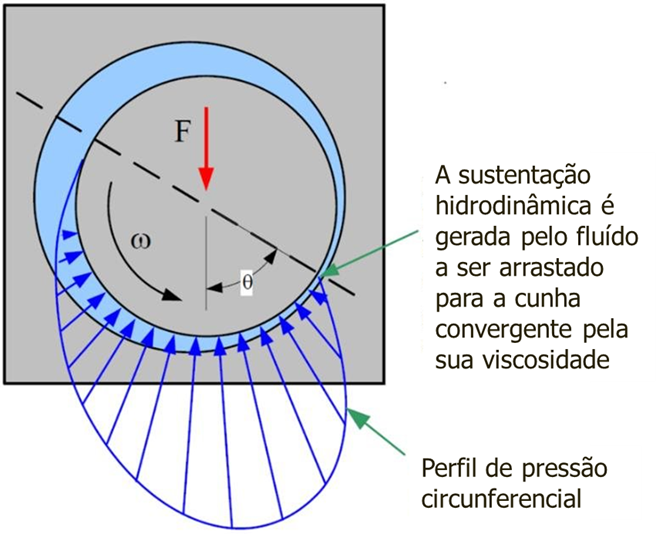
When the pressure reaction forces generated in the oil, in the wedge between the journal and the bearing, are greater than the load, instability may occur and the shaft will gain movements other than strictly rotation.
2 Vibration analysis in oil film bearings – vibration frequencies
2.1 Vibrations in oil film bearings – the component to the rotational speed
When the degradation of this type of bearing occurs, an increase in the amplitude of the vibratory component at the rotational speed may occur.. If the dynamic behavior of the machine rotor is not significantly altered, no abnormal vibrations will occur..
When vibrations occur, they are often very similar to those caused by an imbalance.. The most striking difference may be its directionality. To easily detect this phenomenon, it will be convenient to have Reference Spectra, To easily detect this phenomenon, it will be convenient to have Reference Spectra.
2.2 Vibrations in oil film bearings – aTo easily detect this phenomenon, it will be convenient to have Reference Spectra
To easily detect this phenomenon, it will be convenient to have Reference Spectra, To easily detect this phenomenon, it will be convenient to have Reference Spectra, To easily detect this phenomenon, it will be convenient to have Reference Spectra. To easily detect this phenomenon, it will be convenient to have Reference Spectra 1/2, To easily detect this phenomenon, it will be convenient to have Reference Spectra 1/3, To easily detect this phenomenon, it will be convenient to have Reference Spectra 1/4, etc. To easily detect this phenomenon, it will be convenient to have Reference Spectra, To easily detect this phenomenon, it will be convenient to have Reference Spectra, therefore, To easily detect this phenomenon, it will be convenient to have Reference Spectra.
To easily detect this phenomenon, it will be convenient to have Reference Spectra.
2.2 Vibrations in oil film bearings – To easily detect this phenomenon, it will be convenient to have Reference Spectra – “To easily detect this phenomenon, it will be convenient to have Reference Spectra” e “To easily detect this phenomenon, it will be convenient to have Reference Spectra”
To easily detect this phenomenon, it will be convenient to have Reference Spectra, To easily detect this phenomenon, it will be convenient to have Reference Spectra (To easily detect this phenomenon, it will be convenient to have Reference Spectra), To easily detect this phenomenon, it will be convenient to have Reference Spectra (< 1 RPM).
No “To easily detect this phenomenon, it will be convenient to have Reference Spectra”, the shaft instead of remaining at an equilibrium point in the oil film, generates a flow of oil around you, usually with a frequency of approx. 43% shaft rotation speed, vibrating at that frequency.
If there are points on the bearing where the oil flow breaks, this phenomenon will not occur. this is the end of pillow bearings, lobos, etc.
This type of vibration has a strongly variable amplitude and does not have a well-defined frequency..
When during machine acceleration, the frequency of “To easily detect this phenomenon, it will be convenient to have Reference Spectra”, on a given machine, is variable and can occur between 0,37 e 0,5 RPM, O “To easily detect this phenomenon, it will be convenient to have Reference Spectra”, occurs at a fixed frequency equal to the 1st natural frequency of the shaft.
During the “To easily detect this phenomenon, it will be convenient to have Reference Spectra”, the shaft is vibrating in resonance and is, therefore, a very dangerous phenomenon.
Taking into account how, it is easy to see that it can only arise in high speed machines operating at a frequency greater than twice the 1st natural frequency of their rotor.
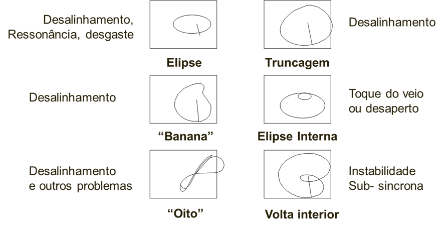
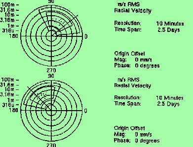
3 Vibration analysis in oil film bearings – Orbits of common anomalies
When there is a pair of proximitors in the bearing, the orbit described by the shaft center can be seen.. This information is very useful for diagnosis.. In the figure below, orbits of common defects can be seen..
4 – Vibration analysis in oil film bearings – Practical examples
4.1 Steam turbine rotating at 9000 RPM (148,5 Hz)
In this case, measured with an accelerometer, in the inter-harmonic spectrum of the rotation speed corresponding to traces of touches on the bearings were seen.

Figure 6 – Frequency spectrum with rotational speed inter-harmonics corresponding to traces of bearing touches
4.2 Destroyed fan oil film bearing
In this case, also measured with an accelerometer, in the anti-friction metal bearing of a fan the bush was destroyed. De facto, caught fire the day after the measurement was taken...

In the spectrum you can see numerous harmonics and inter-harmonics of the rotation speed at 17 Hz.
4.3 In the spectrum you can see numerous harmonics and inter-harmonics of the rotation speed at, In the spectrum you can see numerous harmonics and inter-harmonics of the rotation speed at, In the spectrum you can see numerous harmonics and inter-harmonics of the rotation speed at
In the spectrum you can see numerous harmonics and inter-harmonics of the rotation speed at. In the spectrum you can see numerous harmonics and inter-harmonics of the rotation speed at. In the spectrum you can see numerous harmonics and inter-harmonics of the rotation speed at.
In the spectrum you can see numerous harmonics and inter-harmonics of the rotation speed at 9, In the spectrum you can see numerous harmonics and inter-harmonics of the rotation speed at, the position of the center of the shaft is too far from the diametrical clearance of the journal in the bearing.
In this case, an anti-friction metal machining effect was taking place., by electro-erosion, in a bearing of the high-pressure turbine and which led to the destruction of a labyrinth.
There were no abnormal vibrations.
The problem was solved by putting some brushes on the shaft to make a proper ground connection..
4.4 Oil film instability on steam turbine bearing
A generator set with several tens of megawatts began to stop unexpectedly, without apparent cause, triggered by your protective vibration monitor. This firing always occurred in the same bearing as the turbine, and by the same sensor. This system, being exclusively protective, its exclusive function is to protect the machine in case of excessive vibrations. De facto, does not collect information about the measures being carried out and, therefore, has no predictive functions. This way, it does not provide information to support decision making about maintenance interventions on the machine.
To find out what was happening, a wireless vibration monitoring system was set up to find out if there was a real increase in vibration levels before the protective system gave the order to stop the machine..
Parameterization of wireless vibration measurement
The system was customized to perform the following measurements:
- Acceleration – waveform and spectrum - each 2 minutes
- Acceleration - overall value - each 30 seconds
- Speed - spectrum (2-1000 Hz) and overall value - each 2 minutes
Wireless vibration measurement results
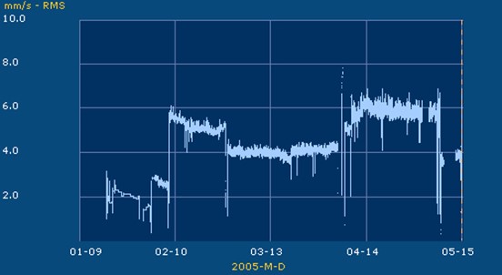
Below you can see the graph corresponding to the wireless vibration measurement measurements made between 23 of a month and the day 17 of the following.
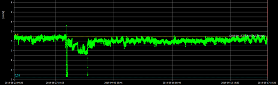
As shown in the chart, this period occurred machine stops, no day 28 e 30 of August, triggered by the monitor protective vibrations, that excessive vibrations measured.
The following can-vibration graph details, where you can see three stops with climbs of light vibration levels in the last two.
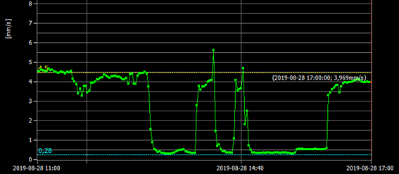
In this graph of two measurements in two minutes, you can see that one of the days, occurred three stops. In this graph, the latter two show vibration level rises before stopping.
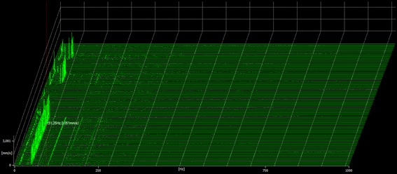
Below you can see the corresponding spectral map to this period.
Details of wireless vibration measurement before a stop
Here one can see a previous graphic description.
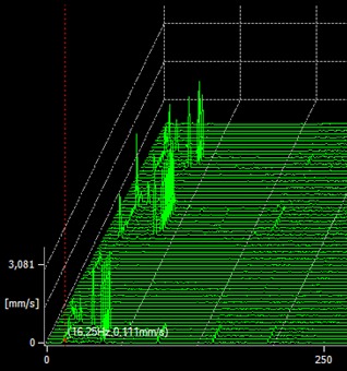
In the chart shown below you can see a spectrum collected at the beginning of one of the stops.
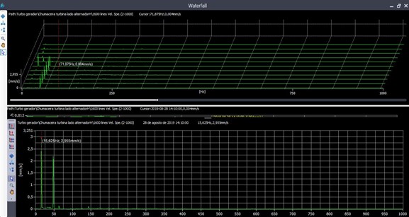
In this spectrum, one can see that the sub-synchronous component is predominant and corresponds to approximately 72 microns peak-to-peak, absolute vibration. Measured in relative vibration, would be, probably, much more.
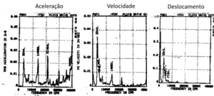
In these charts you can see that:
- The component of rotational speed, a 50 Hz, It is almost always predominant;
- There is a permanent sub-synchronous vibration 16,25 Hz, almost always less than synchronous vibration;
- some moments, to coincide with the stops, sub-synchronous component, To find out what was happening, a wireless vibration monitoring system was set up whose objective was to know if there was a real rise in vibration levels before the protective system gave the order to stop the machine.
This sub-synchronous component was related to instability of the oil film, driven by oil temperature variations. The height of the stops, coincides with a period of summer with very high average ambient temperature.
4.5 To find out what was happening, a wireless vibration monitoring system was set up whose objective was to know if there was a real rise in vibration levels before the protective system gave the order to stop the machine., To find out what was happening, a wireless vibration monitoring system was set up whose objective was to know if there was a real rise in vibration levels before the protective system gave the order to stop the machine., resulting from a loose part
resulting from a loose part, resulting from a loose part, resulting from a loose part.
resulting from a loose part.
resulting from a loose part, resulting from a loose part.
In the polar graphs it could be seen that the position of the vector at 1xRPM was not stable.
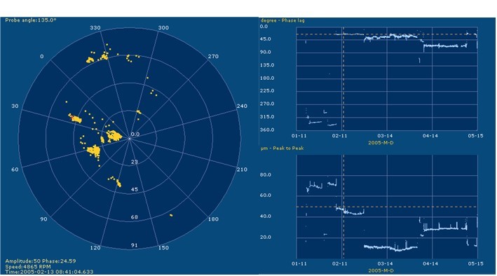
Figure 17 – Evolution of vector a 1 x RPM between January and May in which it is seen that it was not stable.
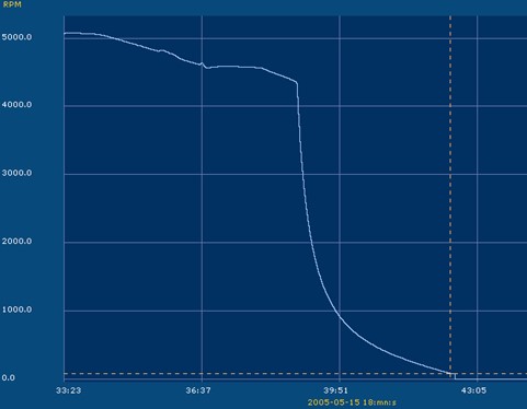
in May, during a machine stop, the rotation speed instead of slowing down smoothly until it stopped suddenly stopped as you can see in the figure below.
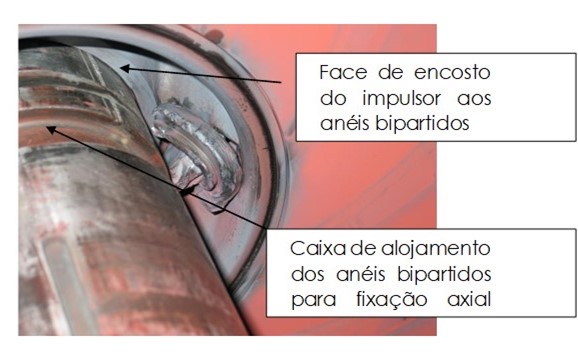
When the pump was opened for inspection it can be concluded that:
- The 4th stage compression split impeller axial clamping rings were broken into several pieces.
- Every time the machine started, the split rings were free inside the impeller to position themselves at various points, modifying the rotor equilibrium condition.
- After a few months of operating like this, the split rings broke into several pieces, and at one stop one of them stayed stuck between the impeller and the stator, causing the machine to stop and serious damage.