Vibration analyzer 9 – order analysis and tracking
The specific topic dealt with in a vibration analyzer 9, consists of the analysis and follow-up of orders.
When it takes place
Vibration Analysis, to take advantage of the full potential of a vibration analyzer, you need to understand how it works. Therefore, here are presented the concepts of digital signal analysis, currently implemented in a
vibration analyzer FFT, from the user's point of view, in a vibration analyzer when performing
predictive maintenance.
We begin by presenting the properties of the Fast Fourier Transform (FFT) on which Vibration Analyzers are based. Then, it shows how these FFT properties can cause some undesirable characteristics in the analysis of the spectrum, like aliasing and breakouts (leakage). Having presented a potential difficulty with the FFT, shows what solutions are used to make vibration analyzers practical tools. The development of this basic knowledge of the characteristics of the FFT makes it simple to obtain good results with a vibration analyzer on a wide range of measurement problems.
- What is the relationship between time and frequency
- How sampling and scanning works
- What Aliasing is and what effects it has
- How it is used and what the zoom consists of
- How waveform windows are used
- What are averages for
- What is real-time bandwidth
- What overlay processing is for (“overlap”)
- What is order tracking
- What is envelope analysis
- The two-channel functions in the frequency domain
- What Orbit is for
- What are the functions of a channel in the time domain
- What the Cepstro consists of
- What are the units and scales of the spectrum
Here you can see the range of
Vibration analyzers made available by D4VIB.
9 Analysis and follow-up orders (“order analysis & tracking” )
9.1 Mastering orders in a vibration analyzer
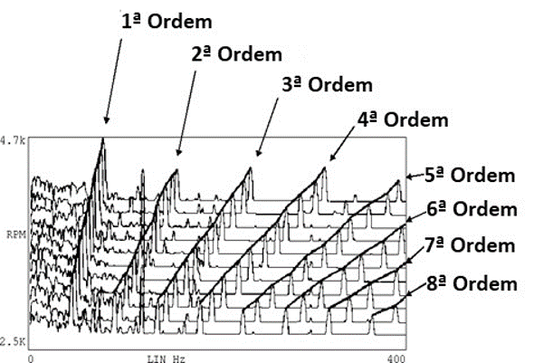
The frequency can also be normalized to the speed of rotation after a measurement. In the graph of Figure 9.1, note that the frequency axis and the reading are in terms of rotation orders (multiples of rotation speed), instead of frequency.
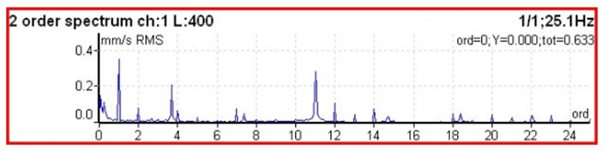
Vibration analyzer 9 – Figure 9.1 Spectrum on which the horizontal axis (frequency) is calibrated in multiples (instructions) of rotation speed
This technique is simply equivalent to scaling the frequency axis when the rotational speed is known or can be deduced and is typically not useful with spectral maps.. This normalization does not work in real time, and the resolution is not a constant percentage of the rotation speed.
The rapid variation in speed, short term, causes an enlargement of the spectral lines in the vibration spectrum, as shown in Figure 9.2. As the speed changes during the acquisition interval of a waveform sample block, for a measurement, the vibration analyzer is effectively analyzing several different spectra. This results in the extended spectral components of the Figure 9.2(b).
a) Constant rotation speed
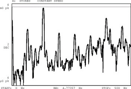
b)Variation in rotation speed
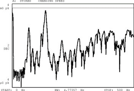
Vibration analyzer 9 – Figure 9.2 The rapid variation in speed of rotation in the short term results in an enlargement of spectral components (b)
9.2 The orders on the spectral map on a vibration analyzer
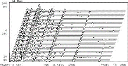
Often what is needed is order tracking (that is, the location of points characterized by amplitude as a function of the speed of rotation for a particular order, see Figure 9.3.
Figure 9.3 The order, is the location of the points on a specific line of the frequency spectrum, depending on the machine rotation speed. The chart shows this data overlaid on a cascading chart.
Orders can also be presented in section as shown in the figure below.
Vibration analyzer 9 – Figure 9.4 of rotation speed
This technique is simply equivalent to scaling the frequency axis when the rotational speed is known or can be deduced and is typically not useful with spectral maps.. For machines that operate at a wide range of speeds, it is desirable to measure vibration over the entire speed range. With a fixed frequency axis, spectral components are in constant motion with changes in speed. For machines operating at a nominally constant speed, even small changes can make comparisons difficult.
9.3 The use of external sampling in a vibration analyzer
Short-term speed variations make real-time analysis difficult. Variations in speed of rotation, long-term, make comparisons between spectra practically impossible.
This is overcome with external sampling synchronized with the rotation of the machine.
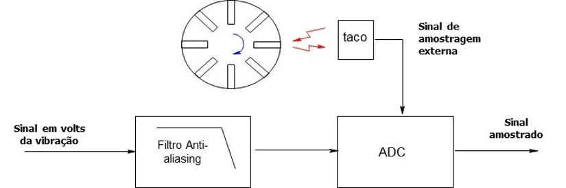
Vibration analyzer 9 – Figure 9.5 – Connecting a tachometer to the vibration analyzer, to be able to control the external sampling depending on the rotation speed of the shaft.
Controlling the sampling of the time block synchronized with the machine rotation (also known as order tracking) can be used to compensate for both problems while the measurement is in progress.
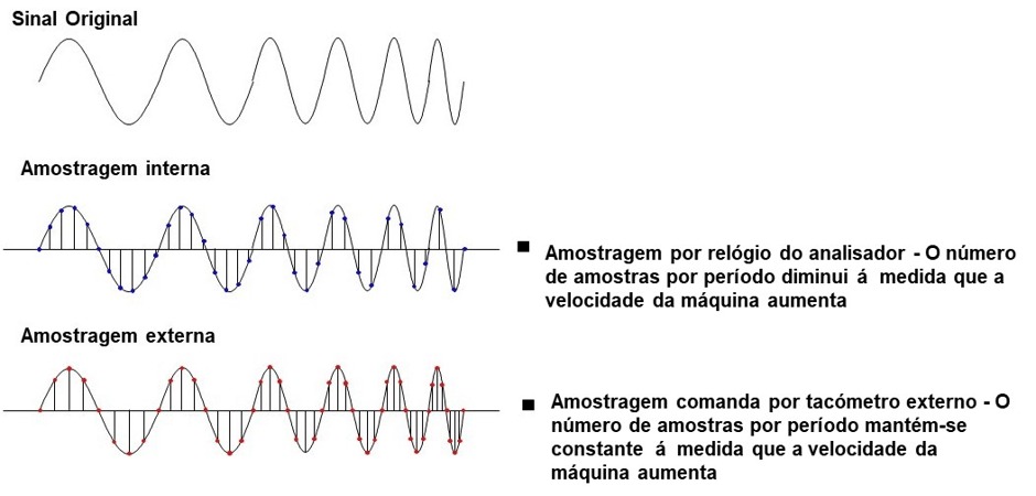
In other words, on the vibration analyzer operating with order follow-up, sampling is not done by the equipment clock, to define a fixed time interval between samples in the block of time that will serve as the basis for calculating the FFT, as shown in Figure 9.3 then presented.
Vibration analyzer 9 – Figure 9.6 of rotation speed
This technique is simply equivalent to scaling the frequency axis when the rotational speed is known or can be deduced and is typically not useful with spectral maps., the frequency spectrum graph will have a fixed calibration in the rotation orders. This is a result of the analyzer, Indeed, sample with a constant delta angle, of shaft rotation.
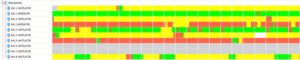
9.4 The effect of external sampling on the spectral map
In the sampling synchronized with the rotation of the machine, what will happen is that the lines of the frequency spectrum related to the rotation speed appear in a stationary frequency.. This is very useful when analyzing vibrations on machines, since most machine defects are related to the frequency of shaft rotation. A good way to illustrate the effects of synchronous sampling control (or external) is with spectral maps made in normal and external sample modes, of rotation speed
This technique is simply equivalent to scaling the frequency axis when the rotational speed is known or can be deduced and is typically not useful with spectral maps.) Sampling by internal clock
b) Sampling controlled by an external tachometer, synchronized with the rotation speed of the shaft

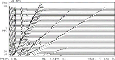
Vibration analyzer 9 – Figure 9.7 Two spectral maps of a machine start-up illustrate the effect of external sampling control, a vibration analyzer.
These two spectacular maps were made during a machine startup. Note that on the map with normal sampling, the frequency components related to the speed of rotation move to the right as the speed increases, while fixed frequency components (for example,structural resonances and related to the electrical supply) appear in a straight line at the same frequency position.
On the map with external sampling control (b), the frequency components related to the speed of rotation, go up directly on the spectral map, while the fixed frequency components move to the left (its relative frequency drops as the speed of rotation increases).
9.5 External sampling and order tracking (“order tracking”)
The main advantage of synchronous sampling control is that the real-time presentation of spectral components related to the order (rotation speed) remain in a fixed position on the horizontal axis. During individual measurements (or especially with average) speed variations do not cause a “enlargement” frequency over a frequency range. Another advantage is the extraction of order ranges is very simplified and the accuracy improves. An order tracking is the graph of an individual order as the speed of rotation changes. Since the frequency of these components has been normalized to a fixed value, a simple marker function can be used to extract an order tracking of the graph from the spectral map as shown in the figure.
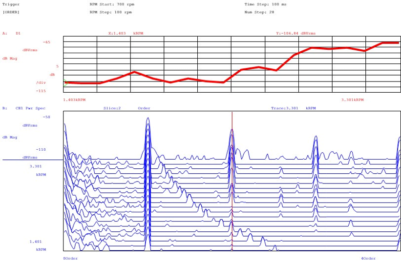
Vibration analyzer 9 – Figure 9.8 A “slice marker” function is used to extract information related to an order on the spectral map graph sampled synchronously (inferior) and build an order tracking graph (superior) for the 3rd order
9.6 Block diagram of external sampling and order tracking
Normally to control sampling, the signal once per rotation is multiplied by a multiplier. The multiplier is necessary because vibration analyzers typically sample at a rate of 2,56 times the frequency range. Since it is generally desirable to look at various orders, or tachometer pulse, once per rotation, must be multiplied by 2,56 times the number of orders to be analyzed. For example, in case you need to analyze a machine for a frequency of 100 instructions, with a signal once per revolution, it would be necessary to multiply the momentum to produce 2,56 * 100 = 256 sampling pulses per rotation. If the block size were 1024 spots, there would be exactly 4 rotations in a data block. An important requirement for the multiplier is anti-aliasing protection. Aliasing occurs when the data sampling rate is too slow, allowing high frequency signals to be misrepresented as low frequency signals. Aliasing is avoided if a filter is used to limit input signals to frequencies below 1/2 the sampling rate as seen above. Since the sample rate is varying, it is necessary to have a variable tracking anti-aliasing filter (tracking filter). The Figure shows a block diagram of this digital implementation of synchronous sample control.
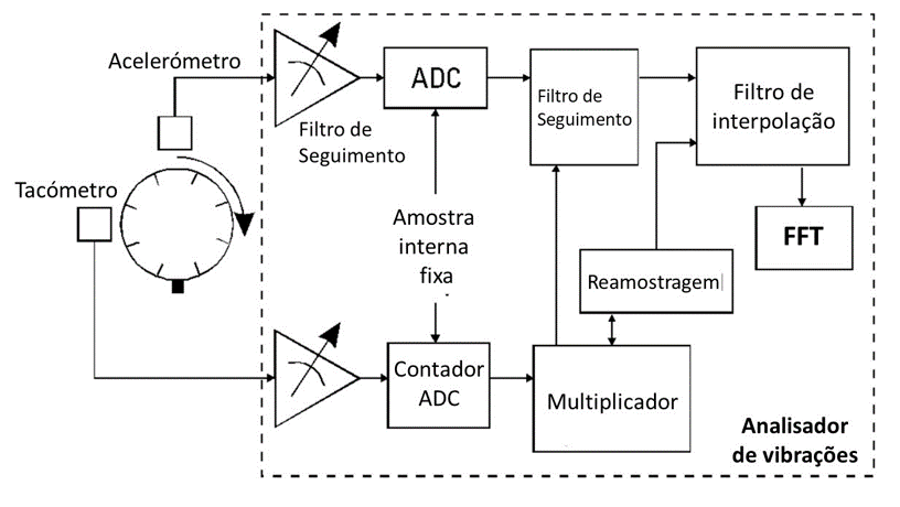
Vibration analyzer 9 – Figure 9.9 Block diagram of the synchronous sample control implementation.
9.7 Measurements of machine starts and stops - the Bodé diagram
An important measurement made using the vibration analyzers' ability to follow orders is that of machine starts and stops. On many machines, the only time they operate at certain important speeds (that is. critical speeds, in structural resonances, etc.) is during a start or stop. This measure is an important indication of the condition of the machines and is generally used to qualify new high speed machines or after overhaul. The measurement uses the residual imbalance in the machine to excite it at different frequencies, since it works up to operational speed and measures the response (magnitude and phase) as a function of speed. This uses the basic order tracking capabilities of the vibration analyzer together with special features for displaying the results of this measurement..
Two common display formats are used with this measure; one is the Bode diagram and the other is the Polar diagram. The Bode diagram depicts the magnitude and phase response of the system at start or stop as a function of speed (RPM).
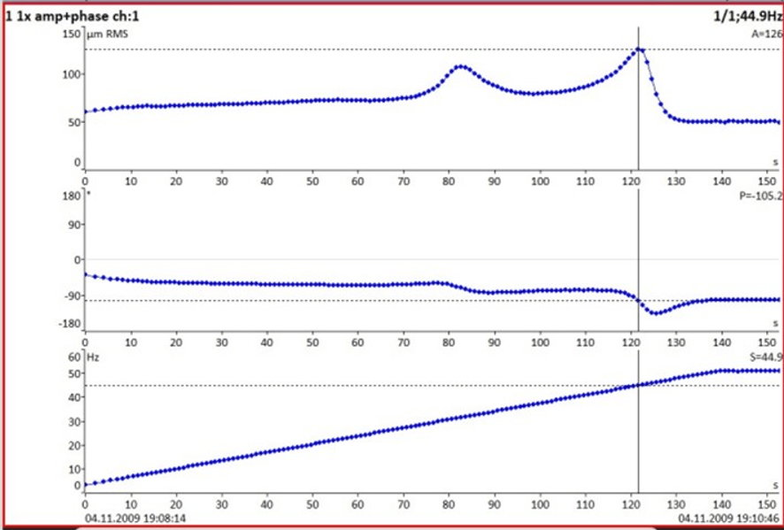
Vibration analyzer 9 – Figure 9.10 – The Bode Diagram of starting a machine, showing critical speeds. The upper graph shows the level of vibrations, the middle one the phase and the lower one the rotation speed. The level of vibrations and the phase are displayed depending on 1 of rotation speed
This technique is simply equivalent to scaling the frequency axis when the rotational speed is known or can be deduced and is typically not useful with spectral maps., is its ability to simultaneously follow multiple orders and display them, beyond the fundamental rotation speed (1ª order); as well as the general level and the rpm profile as seen in the figure.

Vibration analyzer 9 – Figure 9.11 - Bode diagram of starting a machine, with 2nd and 3rd order presentation, as well as the machine's overall level and RPM.
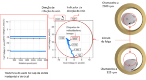
9.8 Measurements of machine starts and stops - the Polar diagram (or of Nyquist)
In the Polar diagram the amplitude of the vibrations is shown as a function of the phase.

Vibration analyzer 9 – Figure 9.12 – Polar diagram (or of Nyquist) starting a machine showing the phase and level in a polar shape. Note the turn given to the graph to compensate for the positioning of the phase and vibration sensors.