Working principle of induction motor
Working principle of induction motor
In this article describes- If the working principle of the induction motor.
Working principle of induction motor – the magnetism
Magnetism is the set of phenomena related to the attraction or repulsion that occurs between materials that have magnetic properties..
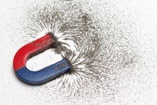
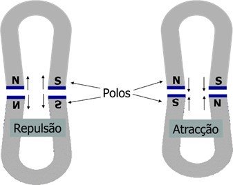
Opposite poles attract and like poles repel.
Working principle of induction motor – the electromagnet
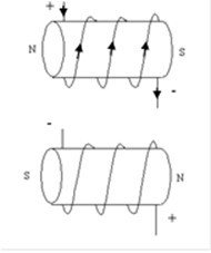
An electromagnet is a device that uses electric current to generate a magnetic field., similar to those found in natural magnets. It is usually constructed by applying electrical wire spiraled around an iron core., steel, nickel or cobalt or some ferromagnetic material.
When the wire is subjected to a tension, the same is traversed by an electric current, which will generate a magnetic field in the area at this spectrum, turn. The strength of the field and the distance it will reach from the electromagnet will depend on the strength of the applied current and the number of turns of the loop..
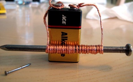
The passage of electric current through a conductor produces magnetic fields in its surroundings and establishes a magnetic flux in the ferromagnetic material surrounded by the turns of the conductor.. The ratio between the intensity of the magnetic flux concatenated by the coils and the current that produced this flux is the inductance.
The piece of iron has the characteristics of a permanent magnet., as long as the current is kept flowing, and the magnetic field can be constant or variable in time depending on the current used (continuous or alternating). By interrupting the flow of current, the one wrapped by the coils can either keep the magnetic characteristics or not., depending on its properties.
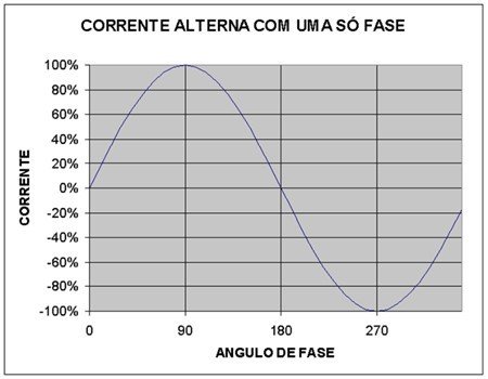
Working principle of induction motor – three-phase alternating current
Alternating current changes phase 50 times per second. In an electromagnetic magnet powered by this current, a polarity change will occur 50 times per second
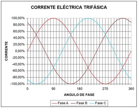
The three-phase power supply can be presented as shown below..
Working principle of induction motor – electromagnetic induction (Lei de Faraday) and electromotive force
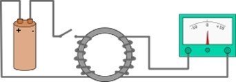
an electrical circuit (turn) subjected to a variable magnetic field undergoes the induction of an electric current.
If two conductors are connected and the rotor rotates in the magnetic field, a circular current results. Below you can see the Diagram of the experiment carried out by Michael Faraday. Changing magnetic flux in the left coil induces an electric current in the right coil..
Lei de Faraday: in a conductor moving in a magnetic field, a potential difference is generated at its ends proportional to the displacement speed. Applied to the stator and rotor of a motor, we have:
- If you have an external magnetic circuit (stator), and a flux is established through coils located on the inductor poles and on the internal magnetic circuit (rotor), cylindrical in shape, there is a short-circuited loop.
- If we rotate the outer part at a speed, constant, An electromotive force will be generated in the internal loop due to the variation in flow, which will circulate a current whose direction will be such that it tries to oppose the variation in flow..
- In practice, the external part does not move, and an immobile three-phase circuit fed with a three-phase voltage system is sufficient. In this way, a rotating magnetic field is obtained.
- The circulation of current through the loop, in the presence of a magnetic field, will give rise to a driving torque that will make it rotate in the same direction as the field.
will exist, therefore, two electromagnetic fields:
- The stator electromagnet;
- The rotor electromagnet.
These two fields repel each other at the same poles. The force generated by the repulsion of equal poles is the electromotive force that underlies the operation of electric induction motors..
Construction of an alternating current induction motor
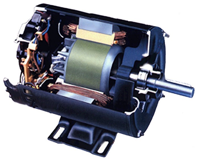
The induction motor is the simplest construction motor. Stator and rotor are solidly assembled, with a vein common to the “rings” that compose them. The stator consists of a winding triphasic evenly distributed around the body of the machine, so that the magnetic flux resulting from the application of voltage to the stator winding produces a wave shape especially sinusoidal. The electromagnetic wave produced by the winding is a sinusoidal function of space and time..
.
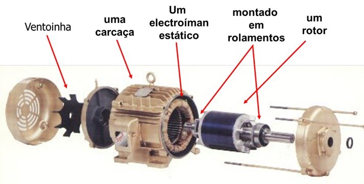
The space between the stator and the rotor is called interferro. The stator is the static part and the rotor is the moving part..
Working principle of induction motor – O rotor
There are two types of induction machine:
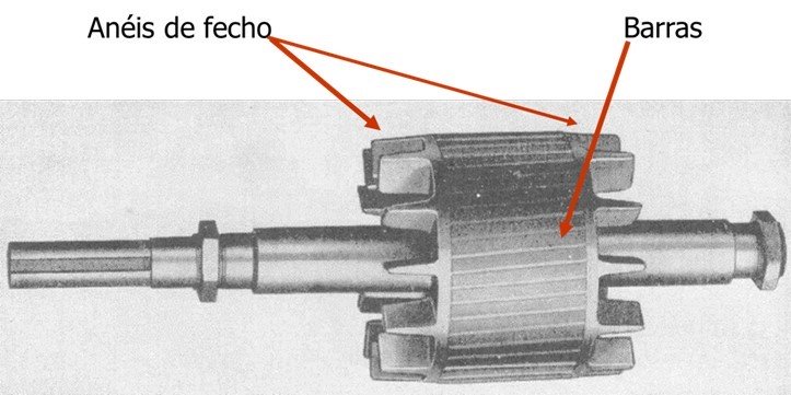
- three-phase induction motor, short-circuited rotor (squirrel cage type): In which the rotor is composed of bars of conductive material that are located around the rotor plate assembly, short-circuited by metal rings at the ends.
- three-phase induction motor, wound rotor: In which the rotor is composed of windings distributed around the rotor plate assembly.
The rotor is also made of thin heat-treated magnetic steel sheets., also shaped like a ring (vista frontal) and with the windings housed longitudinally.
Below you can see a squirrel cage rotor..
The air gap gap
The air gap gap (distance between rotor and stator) is greatly reduced, in order to increase engine efficiency
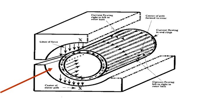
The fundamental principle of operation of a motor is the torque of electromagnetic induced forces.
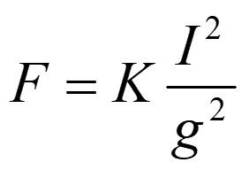
F – Magnetic force
I – Stator current
G – Air gap gap
K – Constant
In a vacuum the magnetic force is very weak.
The element that offers the greatest resistance to magnetic flux is the air gap.. As a consequence, It is important that the air gap value is small. It is also important that it is constant throughout the circumference of the stator, to avoid:
- Magnetic eccentricities,
- Wave Distortions,
- Vibrations
- Warm-ups.
Working principle of induction motor – The stator
O stator is made up of thin sheets of magnetic steel heat-treated or silicon steel to minimize losses due to eddy currents e hysteresis. These plates are shaped like a ring with internal grooves (armholes) in such a way that windings can be housed, which in turn, when in operation, should create a magnetic field not stator.
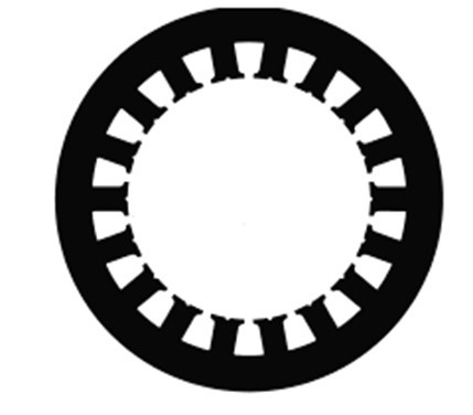
Figure – Stator plate
The magnetic core is made of segments of magnetic sheets. Each segment is isolated with an oxide layer (or varnish). The magnetic core becomes the poles of the stator electromagnet.
The magnetic materials used for the stator core are also conductors. The induced voltage produces current, which causes a rise in temperature, reducing efficiency. The sheet-laminated core reduces current circulation.
Coils are installed in the cavities of the stator core where the electrical supply passes. Coils made up of turns placed in holes (grooves) made on a conductive core.
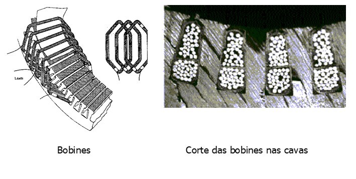
The coils are made from individual windings of coiled copper wire.
- Each coil is isolated from the other coils (enamel)
- Each turn is isolated from the other turns (enamel)
- The turns are grouped into 3 separate electrical circuits (3 phases)
- When the windings are assembled, the stator assembly is impregnated with a varnish
There are four insulation systems in the stator:
- Segment isolation
- Turn insulation
- Coil insulation
- Global impregnation varnish
Normally, the stator is made up of several independent windings inside the slots (armholes) to núcleo, and which are powered by the same electrical network, causing the iron core of the stator to become an electromagnet. The alternating current from the network (50 Hz) induces a magnetic field of alternating polarity in the stator at the rate of 50 times per second.
Below you can see the stator diagram of a three-phase motor.
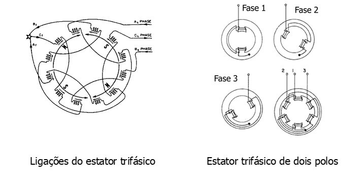
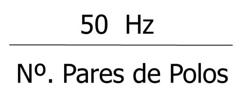
The rotational speed of the electromagnetic field depends on the number of poles in the stator.
2 poles 3000 RPM
4 poles 1500 RPM
6 poles 1000 RPM
8 poles 750 RPM
The formula is as follows:
Below you can see a video about the creation of an electric motor
The generation of the rotating electromagnetic field of the stator
The feeding of 3 phases, of the stator, produces a rotating magnetic field in it, as seen in the figure below.
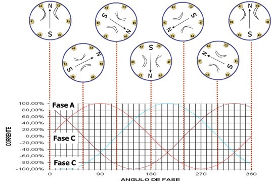
The application of voltage alternate in the stator windings will produce a magnetic field variable in time which due to the uniform distribution of the stator winding will generate a magnetic field rotating resultant at speed proportional to the network frequency triphasic. The rotating magnetic flux in the stator will cross the air gap and, as it varies over time, will induce voltage alternate in the three-phase rotor winding. How are the rotor windings short circuits This induced voltage will cause a current to circulate through the rotor winding, which will consequently produce a magnetic flux in the rotor that will try to align itself with the rotating magnetic field of the stator..
Working principle of induction motor – Starting the engine
When the engine is powered:
- A rotating magnetic field originates from the stator coils;
- When the north pole of the stator passes in front of a rotor bar, a current is induced in the bar. The same is happening at the south pole of the stator with the opposite bar, inducing a current in the opposite direction.
- The result is a circular current in the rotor through a bar, the closing ring and the other bar;
- This circular flow of current through the rotor and around the blades converts the rotor into an electromagnet;
- Electromagnetic forces are maximum when the rotor is stationary (when the engine starts, pass through the three current phases until 10 times the normal).
- The magnetic field of the rotor tries to magnetically align itself with that of the stator.
- The rotor increases rotation speed in an attempt to align itself with the stator field..
- The current intensity in the rotor decreases as speeds approach. Also the intensity of the rotating magnetic field – the torque decreases.
- It reaches a point where the torque generated by the difference in speeds is equal to the power requested from the engine – the rotation speed stabilizes.
- The rotor can never reach the rotational speed of the stator field – it is this difference in speeds that generates the torque, if it reached the torque generated would be zero.) – Slip
When an engine starts from rest, the current induced in the rotor bars is normally 6 times greater than the nominal consumption indicated on the plate for full load, producing a large amount of heat.
This is why large engines have a limited number of starts per hour., the maximum stabilization temperature between starts, or a timed star-delta system to limit consumption at start-up to protect the motor from excessive heating that could damage the stator insulation or rotor bars.
Working principle of induction motor – The engine rotation speed
This way the induction motor will always rotate at a speed lower than the rotating field, and give it the name asynchronous.
The speed of the sync field (ns) depends on the following parameters:
ns=120*f/P
f power frequency (Hz)
P number of inductor poles
The difference between the rotational speed (n) and synchronization (ns):

The engine rotation speed data indicated on its specification plate refer to full load conditions.
For example, a motor 8 poles, 1700 CV e 6000 volt will consume 140 full load amps. If the load is reduced, consumption will decrease and the engine will increase its speed slightly above that specified on the plate. In this type of engine, the rotation speed always varies depending on the load..
Here you can see a video on this topic.
If you want to know more about electric motor analysis click here
If you want to know more about vibration analyzers click here.

