voltage measurement in shafts

The voltage measurement in shafts in electric motors, driven by variable frequency, It should be performed as early as possible in the operating cycle of a system variable frequency / motor and each time a new engine is installed, after an engine repair or replacement of the bearing and after commissioning of new facilities or installation of new production equipment.
The DMC provides the voltage measurement service in veins.
A standard NEMA MG1 Parte 31.4.4.3, identifies the level of capacitive voltages that can cause electrical discharges in a motor bearings, as those that exceed a peak 10 a 40 V (or 20 a 80 V pico-a-pico). The measurement of tension in veins is the best way to confirm the need for additional insulation, such as grounding rings shaft AEGIS®, in electric motors driven by variable frequency, to prevent bearing damage by electro-erosion and ensure the best uptime and reliability. The AEGIS® Shaft Voltage Tester ™ digital oscilloscope is specially designed for measuring voltage in veins.
Electro-erosion in bearings
Due to the high frequencies generated in the pulse width modulation inverters, The frequency inverters induce stresses in the shaft capacitively coupled electric motors that control. The high switching speeds of power bipolar transistors used in these drives, produce common mode voltages on the motor shaft, during normal operation, via the parasitic capacitance between the stator and the rotor.
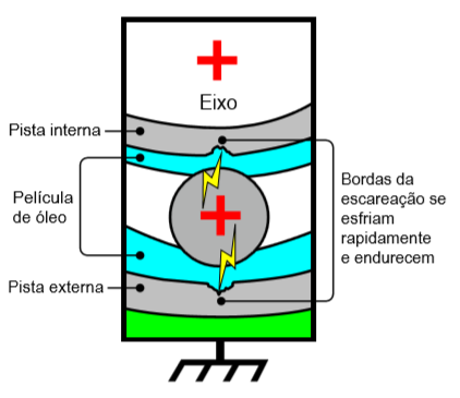
Once these voltages reach a sufficiently high level, They can overlap the dielectric properties of the dough rolling and forming an electrical arc, it is being discharged along the path of least resistance, to the motor frame. For almost every frequency inverter switching cycle, the voltage induced in the shaft is discharged from the motor shaft to the outer housing through the bearings, leaving melting a small crater (wear) the bearing race. When it happens, the temperatures are sufficient to melt the steel bearing and severely damaging or killing the lubricant.
Damage caused by EDM
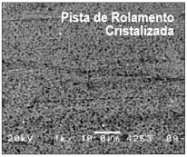
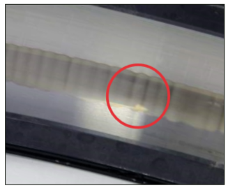
these discharges, They are so frequent (potentially millions per hour) which damages the entire surface of the bearing race, countless known as crystallization escareações. It can also experience a phenomenon known as striation, producing streaks along the crystallized raceway. The rifling cause audible noise and vibration and is an indication of a failure mode effects catastrófico.Estes are easily identified by Vibration Analysis.
 |
 |
 |
failure rates vary widely depending on many factors, but there is evidence to suggest that a significant proportion of failures, only occurs 3 a 12 months after starting the system. All AC motors and DC operated by inverters or electronic inverters, They have the potential to develop this failure in its bearings, regardless of the size of the engine structure or its potency.
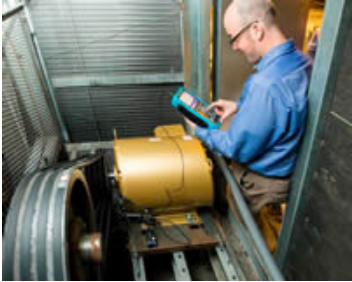
These voltages, They can register peaks 10 a 40 V, They are easily measured and abutting one AEGIS® Shaft Voltage Probe ™ probe on the motor shaft while it is running.
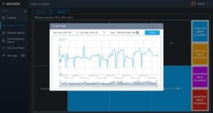
O AEGIS-OSC-9100 Shaft Voltage Tester™, a digital oscilloscope 100 MHz, allows the voltage measurement in shafts is effected with ease and recorded for analysis.
Bearing damage by electro erosion
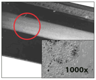
The electro-erosion damage, It consists of millions of microscopic electric escareações, that are created when the current is discharged through the motor bearings. The voltage exceeds the bearing lubrication dielectric and instantly form an arc through the inner race, and passing through the rolling elements to the outer race. The individual usually present between escareações 5 e 10 microns in diameter.
Crystallization:
It appears as a gray band discolored around all or part of the rolling track and may be evident both in the inner race when the outer. The discoloration can be caused by mechanical wear or by electro-erosion. an examination under a microscope may be necessary, to determine if the band is generated by electro-erosion or mechanical in nature. If the engine was operated by a frequency converter, without bearing protection, there is a high probability that the crystallization is by electro-erosion.
Damage rifling:
Identified by a characteristic pattern of streaks. The ribs may be identified by the naked eye or with 10x magnification. Sometimes stretch marks are confused with mechanical bearing damage, such as curing / false cracks, so that should take care to properly attribute the damage to the electrical groove pattern observed. The symptoms of this damage is easily identified with a vibration analyzer.
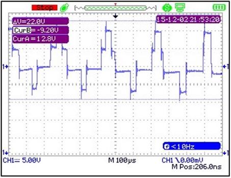
Example 1 measuring voltage on shafts – High voltage common mode, peak to peak
Typically, 20 a 120 V pico a pico (peak 10 a 60 V). This form of the voltage wave measuring shaft, It shows the common mode voltage, capacitively coupled to the motor shaft. The waveform "six steps" is the result of 3 phases of the frequency inverter pulses. Synchronization of pulse width modulation pulses to the motor from the drive determines the appearance of the waveform. Sometimes the waveform will look like a square wave.
This square wave or six steps, is what is seen when there is no discharge of the bearing and the peak to peak voltage on the shaft is at its maximum level. The voltage level can eventually surpass the dielectric in non-insulated bearings and start unloading.
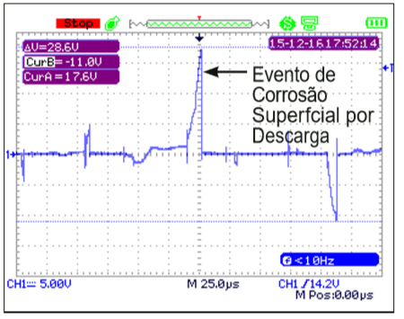
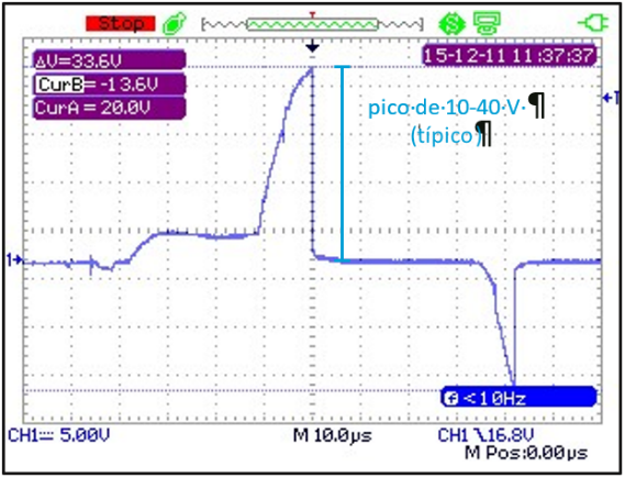
Example 2 measuring voltage on shafts – Discharge Standard electro-erosion high amplitude
Usually, electro-discharge erosion may occur 20 a 80 V pico a pico (peak 10 a 40 V), depending on the engine, bearing type, the age of the bearing and other factors. This form of the voltage wave measuring shaft, It shows an increase in tension in the shaft and then, a sharp vertical line, displaying a discharge voltage. This can occur thousands of times a second, based on the carrier frequency of the drive. The sharp vertical discharge voltage in the output edge is an ultra high frequency dv / dt with a "discharge frequency" Typical 1 a 125 MHz (Based on the test results in various applications).
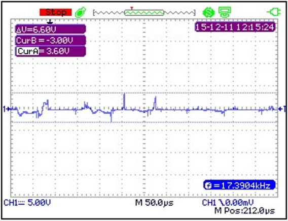
Example 3 measuring voltage on shafts – low amplitude voltage discharge Standard
Typically, strains are 4 a 15 V pico a pico (peak 2 a 8 V). The waveform image shows a more continuous discharge pattern of frequencies dv / dt smaller. The lower voltage may be due to the increased current flow in the bearings which is the result of bearing lubrication, which becomes conductive or could be a function of motor drive, velocity, loading or other factors. As discharges occur in the bearings, the lubricant is contaminated with carbon and metal particles. The lowest impedance for voltages in the shaft, results in lower peak voltage peak. This condition is usually found in engines that have been in operation for many months or years.
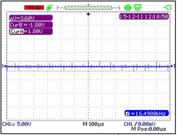
Example 4 measuring voltage on shafts – Voltage peak to peak with AEGIS® ring installed
With AEGIS® ring installed, a vein of steel usually show tensions shaft 2 a 10 V pico a pico (peak 1 a 5 V), depending on the engine power, ground noise, conductivity of the shaft and other factors. The readings of voltage measurement in shafts can be further reduced by applying the coating shaft colloidal silver AEGIS® , allowing higher conductivity of the surface of the shaft and a more efficient electron transfer, to the ends of the conductive microfiber.
The waveform image shows the waveform peak to peak Low, AEGIS® with SGR ring installed and discharging voltages of the shaft in the normal manner.
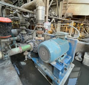
Operating Motors with frequency inverters
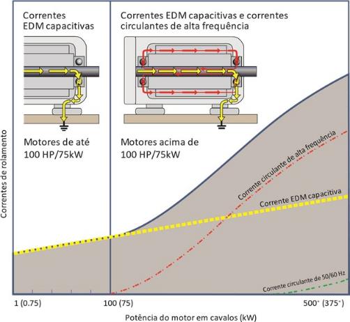
The alternating current motors, operated through frequency inverters use pulse width modulation to control the motor speed. This means that there are common mode voltages, which are capacitively induced on the motor shaft and can be discharged at the motor bearing surface causing corrosion damage, crystallization and scoring by electro-erosion, resulting in breakdowns. Besides that, The above motor 75 kW and medium voltage motors, They may also have current high frequency currents, which can also cause damage surface erosion, crystallization and scoring by electro-erosion. DC motors, may also be capacitively induced voltage shaft, which can be downloaded at the motor bearings and, Besides that, above motor 7,5 kW, circulating currents may also be.
Voltages induced in the shaft and variable frequency currents in the bearings -
Three current sources bearings:
There are three sources of bearing currents, referred to herein, two of which, current capacitive electro-erosion and high frequency circulating current, They are caused by variable frequency. The third type, what is termed circulating current 50 / 60Hz, It occurs mainly in large alternating current motors that are operated by the mains voltages 50/60 Hz.
Current electro-erosion capacitive (the frequency inverter):
capacitive induced voltage from the switching waveform of the pulse width produced by the frequency inverter. This voltage is coupled to the motor shaft through parasitic capacitance and can be discharged in the motor windings or bearings in the driven equipment, causing machining by electro-erosion.
Current high-frequency current (the frequency inverter):
The high frequency circulating current can flow due to a high flow rate, produced by common mode current. The circulating currents of high frequency inductive, of variable frequency, They are in the kHz or MHz range and can be present in up engine 75 kW. Usually, the higher the engine, the greater the effects of circulating high frequency currents.
circulating current 50/60 Hz (mains voltage):
voltage sources of sinusoidal waves 50/60 Hz, in large machines, They can cause extremely low frequency circulating currents, due to the asymmetrical design of the motor and magnetic asymmetries.
bearing protection for new and reconditioned engines
It is essential that the engines operated by frequency inverters or direct current, They are designed to protect the bearing, of both types of current sources. Installation of bearing protection rings AEGIS®, It provides a connection path to ground proven and reliable, for discharging the capacitively induced voltages safely, away from the motor bearings, to the ground. Engines with circulating currents, They should also have housing insulation or shaft, or an isolated bearing, installed at the opposite end of the roll guard ring AEGIS®, to stop the high frequency circulating current path. This approach, is the recommended best practice for motors driven by frequency inverter to protect the most critical mechanical component of the engine - the motor bearings.
engine grounding driven by variable frequency
Proper grounding, high frequency motors driven by variable frequency, It is vital to avoid discontinuities in the ground level between the system components. It is especially critical, in applications involving an engine and attached equipment, that are not mounted on a common base plate. In such cases, effective grounding of the high frequency is required, of all system components, to equalize the electrical potential between the equipment and structures to prevent ground loops between the engine and attached equipment. earthing strips of high frequency (as HFGS AEGIS®), widely recognized as the most efficient route for grounding, for high frequency currents, They are recommended by leading manufacturers of actuators and motors.