Types of accelerometers
Types of accelerometers
Introduction
The subject covered in this article consists of a description of some of the types of accelerometers that exist.
O accelerometer is a device used to measure at accelerationoh you vibration analysis. Can work from various physical effects and are able to measure a wide range of acceleration values, logo having a very high range of applications. These devices are widely used in positioning systems, tilt sensors, as well as vibration and shock sensors. For example, the orientation of mobile phone screens that adjust according to the angle they make in relation to the acceleration of gravity is carried out with accelerometers. Another example is the trigger sensors of “air-bags” of cars.
- Types of accelerometers
There are many types of accelerometers that use different types of physical effects to measure acceleration..
Types of accelerometers – the aresistive celerometers
A resistive accelerometer makes use of the variation of a resistance when deformed.
The first development of the extensometry bridge-type accelerometer, which ended up being marketed, originated in the USA in 1923 and weighed about half a kilo. It consisted of an E-shaped structure containing 20 a 55 carbon rings in a tension-compression Wheatstone half bridge half bridge between the top and center section of the frame. A figure illustrates this device. It was applied in bridges, dynamometers and aircraft. Its resonant frequency was less than 2000 Hz. In 1936 a catalog advertised a two-axis accelerometer with “adjustable cork damping” at intervals, up until 100 g. The advertised applications were: "acceleration record of an airplane catapult, passenger elevators, Aircraft Steam Turbine Vibration Dampers, underground pipes and blast forces…”.
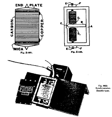
Figure 1. McCollum-Peters carbon cell-based accelerometer (1936).
Large-scale marketing of accelerometers, However, it only took place with the advent of the bonded resistance strain gauge. The discovery of this type of strain gauge occurred in the USA in 1936.
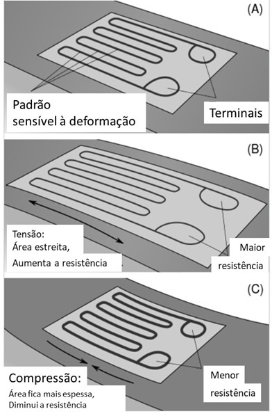
Visualization of the working principle of a strain gauge on a beam under exaggerated bending
The problem with all strain gauge accelerometers was that they provided signal outputs of approximately 30 mV. Therefore, depending on the application, signal-to-noise ratios could be an issue. Even to achieve these signal levels, seismic systems using low-rigidity components were needed. The bending of these components resulted in low resonant frequencies and mechanically fragile accelerometers. To increase your frequency response and, at the same time, lessen your frailty, accelerometers were often dampened with fluid.
Today there are piezo-resistive accelerometers manufactured with MEMS technology (micro-electro-mechanical systems).
Some considerations in selecting piezoresistive accelerometers (MEMS):
• DC Response (zero thermal stability must be considered)
• Not normally used outside of -54 a + 121 °C and requires compensation
• Typical signal levels ~ 200 mV end of scale
• Often recommended for severe mechanical shock
• Typical applications in the automotive and defense industry
• Available in wide range of Gs
• Preferably in VERY large quantities (for example, airbag shot)
Piezoeletric accelerometer
This type of device makes use of the piezoelectric effect. Normally, there is a mass attached to a piezoelectric crystal. When there is an acceleration in the system, the mass attached to the crystal ends up generating a deformation and this displacement generates an electrical signal.
The solution to the problems of older resistive accelerometers, resulted from the introduction of the piezoelectric accelerometer. The piezoelectric materials used have high rigidity. Besides that, their self-generated electrical responses produced wide dynamic signal ranges. Both of these properties combined allow the design of accelerometers with high resonant frequencies.. These high resonant frequencies have eliminated the need for damping to increase the accelerometer's usable flat frequency response.. The phase shift in the accelerometer's usable frequency range has also been eliminated. This large dynamic signal range also allowed for the reduction in size of piezoelectric accelerometers compared to strain gauge accelerometers., while providing the ability to measure much larger accelerations.
The world's first commercial piezoelectric accelerometer was developed in Denmark, by Dr. Per V. Brüel, in 1943.
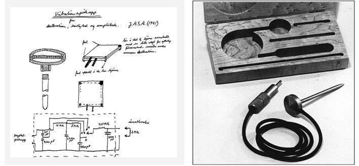
Figure 2 - Operating diagram and photograph of the piezoelectric accelerometer model BK 4303
the end of the years 1940 and the beginning of the years 1950 were a time when several manufacturers of piezoelectric accelerometers emerged.. The piezoelectric materials used include ferroelectric and not- ferroelétrico (for example, quartz). The first ferroelectric ceramics used were mainly barium titanate. Charge amplifiers were developed next. (years 50) and then a two-wire integrated circuit (FET) has been incorporated into the accelerometer itself (years 60). The placement of integrated circuit technology inside the accelerometer (ICP), which is the main technology of today, eliminated much of the cable noise based on the bothersome triboelectric effect to the load circuit. Accelerometers with integrated circuits are normally sealed units capable of operating with long cables, in various hostile environments.
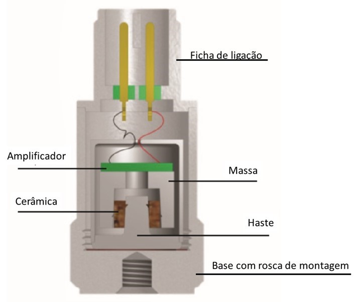
Figure 3 – Example of piezoelectric accelerometer with cut crystal
Some considerations in selecting piezoelectric technology
- Capable of operating from cryogenic temperatures to 700 degrees C
- frequency range of 0,05 Hz a 50 KHz
- wide dynamic range (micro-Gs to thousands of Gs)
- Available under 1 gram
- Integral electronics produces signal from 0-5 volts
- Typical applications are vibration and shock measurement
- very robust!
Today they are the most used in measuring vibrations, in predictive maintenance, com Vibration analyzers.
Capacitive accelerometers
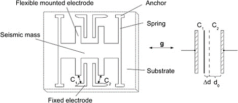
A capacitive accelerometer works so that acceleration in the device displaces a moving plate of a capacitor relative to fixed plates in the device.. of this, how the capacitance of each capacitor changes.
Capacitive accelerometers, depend on a change in electrical capacitance in response to acceleration.. Accelerometers use the properties of an opposite plate capacitor, for which the distance between the plates varies in proportion to the applied acceleration, thus changing the capacitance. This variable is used in a circuit to provide a voltage signal proportional to acceleration..
Capacitive accelerometers are capable of measuring constant transient and periodic accelerations, from DC. AC capacitive acceleration sensors fundamentally contain at least two components; the primary is a board “stationary” (that is, connected to the housing) and the secondary plate is fixed to the inertial mass, who is free to move within the housing. These plates form a capacitor whose value is a function of the distance d between the plates. The detection material is a flat nickel plate or an electronic chip supported above the substrate surface by two torsion bars attached to a central pedestal. A capacitive accelerometer rarely exceeds a maximum displacement of 20 μm. Therefore, such a small displacement requires a reliable measurement of deviations and various interferences.. When subjected to fixed or constant acceleration, the capacitance value is also a constant., resulting in a measurement signal proportional to uniform acceleration, also known as DC or static acceleration..
Figure shows the schematic of a capacitive accelerometer.
Nowadays they are also manufactured with MEMS technology..
Typical Properties:
- Usually provide good thermal specifications -54 a + 121 ºC
- DC responsiveness
- Range: +/- 2 a 200 Gs FS
- Large capacity above the range (for example, 5.000 Gs)
- Usually provides +/- 2 unregulated DC power volts
- Typical Applications: transport, flutter de aeronaves
Hall Effect Accelerometer
on this device, acceleration moves a tape, which is conducting electrical current, by a non-uniform magnetic field. Like this, the greater the displacement, greater will be the magnetic field, therefore, the greater the difference in potential across the current, due to the Hall effect.
The mechanical system of this type of accelerometer consists of a mass suspended from the structure by a flat spring. The acceleration to be measured is proportional to the deflection of the other end of the spring. Mechanical displacements are measured by Hall voltage, with the Hall generator mounted on the end of the spring and moving in a non-uniform magnetic field. When the magnetic field gradient is linear, the Hall voltage is proportional to the measured acceleration.
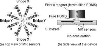
magnetoresistive accelerometer
In the case of a magnetoresistive accelerometer, the acceleration causes a displacement in a mass of magnetic material and, on the fixed part of the device, there are materials that change its resistance, with the presence of a magnetic field.
The Figure shows the schematic of a magnetoresistive accelerometer.
Fiber Optic Bragg Network Accelerometer
Estes, are accelerometers that use fiber optic Bragg gratings to measure acceleration.
Bragg networks in optical fibers, are optical fibers with periodic refractive index variation regions. They have the property of transmitting several wavelengths and reflecting in a well-defined wavelength.. Therefore, it works as a wavelength filter. When suffering a deformation, fiber optic density is changed, and consequently the refractive index, and finally the filtered wavelength. in a simplified way, on this device, there is a beam with one end attached to a base, e, at the other end, there is a mass of evidence stuck. A fiber optic Bragg mesh is glued to the beam.. When the mass is accelerated, the beam and these fibers undergo a tension that stretch them. Like this, the wavelength reflected by the optical fiber changes. These devices are often used to detect seismic activities due to their very high sensitivity combined with low noise. A typical earthquake has frequencies on the order of 0,1 a 1 Hz and accelerations of the order of 0,1 g. Therefore, you need a detector that works in the same frequency range and can differentiate such low accelerations. In this type of accelerometer, you can work on the same track, with wavelength variation sensitivities in the range of 90 a 600 pm/g.
Types of accelerometers – O servo-accelerometer (Force Balance Acelerometer)
In this type of sensor an electrical circuit tries to maintain a mass in an equilibrium position. The current applied to the circuit is proportional to the acceleration, this being so measured.
The force balance accelerometer is shown below, where a pendulum mass of high magnetic permeability is hung on a rod, as shown. A “down position” or “null position” is detected by the null detector and the counterweight force is provided by a magnetic coil.
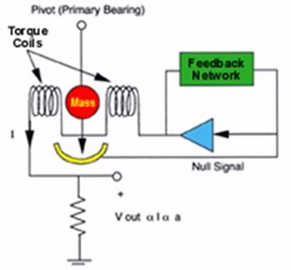
If acceleration is applied to this sensor, a force is exerted on the mass and it will try to move from the null position. When the null detector detects motion, coil current is increased by means of a servo amplifier to maintain the null position.
The coil current provides the restoring force necessary to maintain the null position and this current will be in direct proportion to the applied acceleration.
Highly accurate null detectors can be easily manufactured, since the total range of this deflection is extremely small. In fact, increasing null detector resolutions will result in proportionally improved acceleration resolution.
The servo accelerometer is physically large compared to resistive accelerometers, but provides microgravity resolution with high zero-hertz stability and low thermal errors. The large size of the inertial mass results in large forces during high shock events and this type of sensor is not suitable for high shock environments..
Some considerations in selecting servo accelerometers:
- Most accurate and expensive type of any accelerometer
- Response from DC to a few hundred Hz, typical
- Usually the scale is less than 50 Gs
- Fragile: limited along the range (evolving with MEMS technology)
- Typically provide multiple volt output.
- Typical Applications: guidance (IMUs with gyroscopes), seismographs.
Types of accelerometers – the acelerómetros MEMS
Nowadays, in many applications, accelerometers manufactured with MEMS technology are used (“micro electro-mechanical systems”).
This technique creates microscopic sized mechanical detection structures, usually in silicon. When coupled to microelectronic circuits, MEMS sensors can be used to measure physical parameters, as acceleration
So more than just one type of accelerometer, is an accelerometer manufacturing technique.
Basically they consist of a built-in structure with a mass. Under the influence of an external acceleration, the structure deforms, by the effect of the force exerted by the mass, and this deformation is measured allowing to know the acceleration.
The way to measure the deformation can be different. Nowadays there are types of MEMS accelerometers, resistive, capacitive, servo accelerometers, etc.