Turbine supervision instrumentation
1 Introduction – Turbine supervision instrumentation (TSI)
This article introduces turbine supervision instrumentation..
This article belongs to a series, which constitutes the support material for the course on vibration analysis in turbomachinery. Links to the other articles can be found on here.
The transition from steam to gas
In times, most of the world's electricity production came from steam turbines coupled to generators. Whether steam was produced by burning conventional fossil fuels, like coal, gas or oil, either by the heat of nuclear fission in a reactor, the process was essentially the same: heat water to steam, expand it through a turbine coupled to a generator and recycle the exhausted steam/water to heat it again through the boiler or reactor.
At the moment, production methods to meet global energy demand have largely shifted to gas turbines instead of steam turbines, augmented by a much higher percentage of renewable sources (wind, solar, geothermal).
This change occurred for two reasons.: gas turbines are more efficient than steam turbines at extracting energy from a given amount of fuel, and gas turbines create fewer pollutants (emissions per MW of production).
The most efficient gas turbines in the world, for example, can currently reach efficiencies close to 45%. In comparison, plants composed only of steam turbines rarely exceed the 35% of efficiency.
The persistence of steam turbines
Anyway, there is still a sizable installed base of steam turbines around the world and will continue to exist for the foreseeable future. Besides that, the installation of new steam turbines will continue, since the waste heat from the exhaust gases of a gas turbine can be used to boil water and create steam for a steam turbine. These power stations are known as “combined cycle” because they combine the thermodynamic cycles of gas and steam turbines in the production of electricity. Consequently, are more efficient than the central calls of “simple cycle” – whether they consist only of gas turbines (typical efficiency of 35-40%) or just by steam turbines (typical efficiency of 30-35%).
In contrast, a typical combined cycle plant has an efficiency of 50-60%. This increased efficiency is due to the fact that the heat from the gas turbine, that previously went up the exhaust chimney, be routed through an HRSG (Heat Recovery Steam Generator).
The resulting steam is expanded through a turbine that drives another electric generator., producing more energy without the need for any additional fuel. An identical fuel content in a combined cycle plant produces, like this, more MW of electricity than a similar-sized single-cycle gas turbine power plant.
size is important
One of the ways to optimize steam turbine efficiency is through size.. A large steam turbine is more efficient than several small steam turbines operating in parallel to produce equivalent power.. In a fossil fuel powered power plant, a typical steam turbine has dimensions ranging from 50 MW e 1200 MW (Figure 1.1). Numa central nuclear, a typical steam turbine has a dimension that varies between 800 MW e 1770 MW. The enormous size of these machines means that the rotors are often very long.. Besides that, how the enclosure of a steam turbine is designed as a pressure vessel, it is usually very thick (300 mm or more) and expands/contracts more slowly than the rotor. These and other factors combine to result in a set of measurements that are unique to large steam turbine generators and complement conventional radial vibration., the phase reference, bearing temperature and axial position measurements typical of all rotating machines with fluid film bearings.
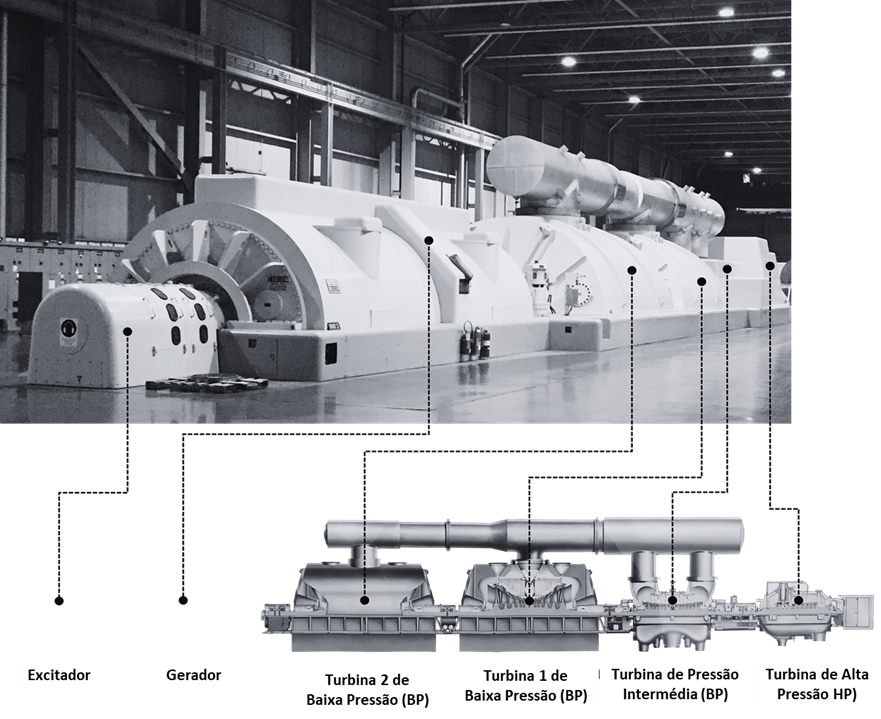
Turbine supervision instrumentation – Figure 1.1 A 525MW steam turbine generator made up of High Pressure bodies (AP), Intermediate Pressure (PI) and Low Pressure BP) (two), together with generator and exciter. Steam enters the High Pressure turbine box at the bottom and exits at the top., where it flows to the two Low Pressure turbines in parallel.
2 Turbine supervision instrumentation – specialist measurements
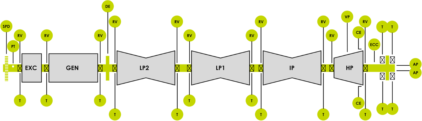
Specialized measurements unique to steam turbine generators are performed with so-called Turbine Monitoring Instrumentation (TSI) and are described below. These measurements, along with conventional vibration measurements, position, temperature and phase reference, are shown in Figure. 2.
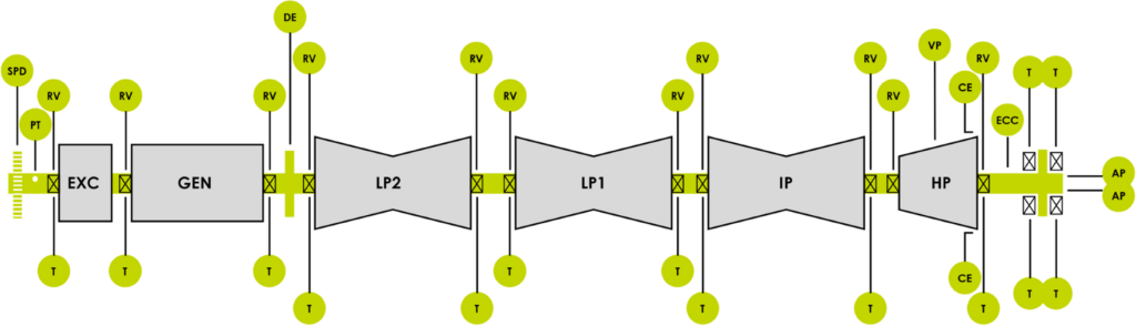

Turbine supervision instrumentation – Figure 1.2 – Figure steam turbine generator set diagram 1.1 showing the location of TSI measurements
Differential expansion (OF)
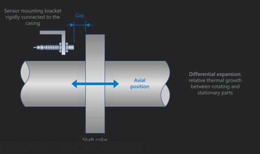
As referred to above, large steam turbines have massive casings, relative to its rotor, which results in different rates of thermal expansion. This is due, partly, differences in metallurgy and corresponding thermal expansion coefficients, but also to the extreme differences in mass and thermal inertia between the rotor (relatively) light and its carcass much heavier.
When superheated steam is introduced into a turbine, their casings and rotors expand at different rates. If the expansion of these parts relative to each other is not rigorously measured and controlled, the rotating parts (for example, the turbine blades) can come into contact with non-rotating parts (diaphragms da turbina) and substantial damage can occur..
To maximize the efficiency of steam turbines, clearances between blades and diaphragms are – per project – quite tight and only a small amount of differential movement can be tolerated.
Differential expansion measurements are often taken close to the low pressure casing because the shaft is axially limited at the thrust bearing location. (near the high pressure turbine) and then it grows (expand) outward from that point along the length of the machine through the PI and BP frames.
However, location may vary depending on the turbine housing being measured for differential expansion. For example, the figure machine 1.1 has differential expansion measurement on the external side of the AP turbine, as shown in Figure 1.2. Regardless of where the ED measurement site is located, the principle is the same: check the relative thermal growth between the turbine frame and the rotor.
As the amount of thermal expansion can be substantial, and beyond the linear range of most conventional proximity probes, it is often necessary to use a special arrangement of two probes to cover the entire differential expansion range.
However, in some cases, only a single transducer can address the required range – particularly when so-called pressure sensors are used. “extended range”. Each type of differential expansion measurement is described below..
Differential single channel expansion (To paste) SCDEC
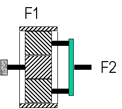
This measurement is performed using a single proximity probe, fixed to machine case, and observing a special collar specifically intended for DE measurement (Figure 2). The space between the tip of the probe and the perpendicular surface of the observed collar represents the relative movement between the casing and the rotor..
Note: When the probe is rigidly attached to the base of the machine, instead of machine case, the contribution due to box expansion is removed from the measurement. This is known as rotor expansion., as it indicates the amount of absolute growth/shrinkage of the rotor only, instead of its relationship with the box, which can also grow/shrink.
Turbine supervision instrumentation – Figure 2 VM600MK2 Setup Software Screenshot (VibroSight PROTECT) representing a Single Channel Differential Expansion measurement (To paste).
Differential single channel expansion (pendulum) SCDEP
This measurement is performed using a special pendulum that changes the angle of the probe's target as the shaft expands or contracts in relation to the machine housing..
The angle changes via a magnet in the shaft collar that pulls the pendulum in either direction as the shaft grows or shrinks.. Using the trigonometric relationships between the various geometries of the probe/target array, changes in probe aperture are converted to actual differential expansion. Thus, a much wider range of expansion can be observed than if the spacecraft were simply observing a perpendicular collar. See Figure 3.
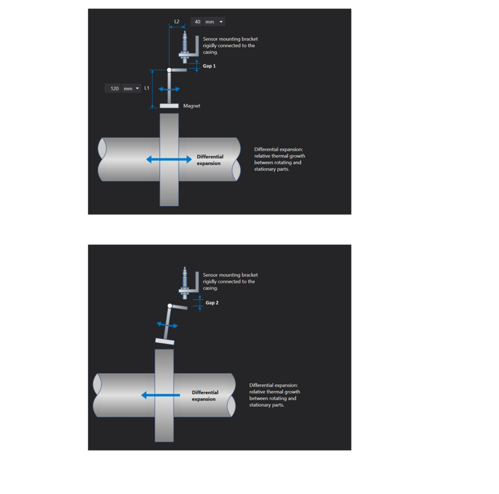
Turbine supervision instrumentation – Figure 3 – Setup software screenshot VM600Mk2 (VibroSight PROTECT) representing a SCDEP measurement. in the bottom image, the axis has expanded to the left, rotating the pendulum clockwise and increasing the probe space (Space 2 > Space 1).
Dual channel differential expansion (to paste) DCDEC
This measurement uses two probes: facing each other and looking at opposite sides of the DE collar.
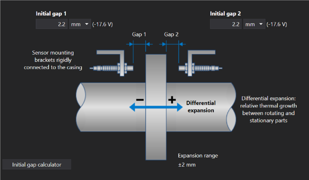
Turbine supervision instrumentation – Figure 4 – VM600Mk2 Setup Software Screenshot (VibroSight PROTECT) which represents a DCDEC measurement.
Dual channel differential expansion (double cone) DCDEDT
When using a conical surface (on ramp) didn't come, a radial probe can observe changes in clearance as the shaft grows or shrinks. Unlike a conventional radial vibration measurement, where the probe gap does not change as the shaft grows or shrinks axially, tapered surface will change probe clearance due to axial movement. Since the probe gap change is related to the sine of the cone angle, the range of a given probe can encompass a considerably greater magnitude of differential expansion.
For example, if the angle of the cone is 12°, the scope of the probe can encompass approximately five times more differential expansion than if it were just looking at a perpendicular DE collar.
However, as the probe clearance is a composite of the radial position of the shaft in the bearing clearance and the axial position of the cone, the signal from a single probe reflects both contributions. To isolate only the effects of the axial position of the cone, and not the radial position of the shaft, a second probe is used, allowing the effects of radial shaft position to be subtracted from the composite contributions of axial and radial changes. The second probe can be used to look at a second cone or a conventional non-conical part of the shaft.
The DCDEDT measurement is represented in Figure 5. Conical surfaces can be of convex design, as it turns out, or concave design (the call “butterfly”), as shown in the insert.
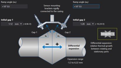
Turbine supervision instrumentation – Figure 5 Screenshot of VM600Mk2 configuration software (VibroSight PROTECT) representing a DCDEDT measurement. In this case, the cones are back to back, forming a convex shape. The arrangement of cones called “butterfly” is shown in the green inset and is used by some turbine manufacturers instead of the convex arrangement, but the probe configuration considerations are essentially the same.
Dual channel differential expansion (single cone) DCDEST
This measurement is similar to the DCDEDT measurement, but uses a conventional radial surface for one probe and a conical surface for the other.
The two probes have the same purpose as in the case of a double cone, but the probe looking at the non-conical surface only contains information about the radial position, while the probe looking at the cone contains information about differential expansion and radial position. With regard to the figure 6, subtracting the signal from the probe 2 to the signal from the probe 1, and through trigonometry for the conic surface, It is possible to determine the differential expansion.
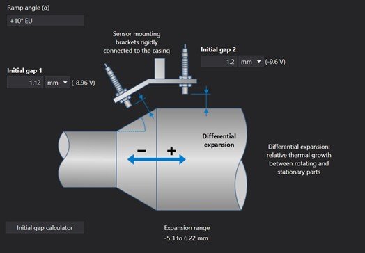
Turbine supervision instrumentation – Figure 6 VM600Mk2 Setup Software Screenshot (VibroSight PROTECT) which represents a DCDEST measurement. In this case, the ramp is on the left.
A Note on Extended Range Probes
One of the reasons why dual-channel DE arrangements are used is that smaller probe diameters can be used. (with correspondingly smaller linear intervals). in some cases, Yet, DE probes with linear ranges greater than conventional DE probes are found or needed. 2 mm or 4 mm. This is often the case with turbines where a simple perpendicular collar is used instead of a conical surface.. for these applications, so-called probes are often used. “extended range” with diameters up to 50 mm and corresponding linear ranges up to 28 mm. These probes can be handled by the VM600Mk2 configuration software (VibroSight PROTECT) as types of transducers “personalized” To easily detect this phenomenon, it will be convenient to have Reference Spectra, therefore, fully compatible with the VM600Mk2 platform.
body expansion (HE)
Steam turbine rotors are usually attached to a thrust bearing on the inner side of the high pressure turbine and can expand from there along the length of the turbine generator set.. Since the high pressure turbine has the hottest steam, is the one that undergoes the greatest expansion and can be designed to be fixed at one end of the box, allowing the other end to expand into the turbine's sliding feet. If one or more feet get stuck, problems such as a crooked carcass may arise (armada) or a stuck casing as a result of friction between the casing and the rotor and/or a permanently deformed casing.
Casing expansion on large turbines can be well over 25-50mm and is most often measured using an LVDT (Figure 7) to monitor that the turbine housing is sliding properly (expanding or contracting) on your feet.

Turbine supervision instrumentation – Figure 7 The AE119 is typical of LVDTs used for box expansion measurements.
Measurements can be brought into the VM600Mk2 as a native LVDT voltage signal or as a quasi-static process variable signal from LVDTs with an output of 4-20mA.
While it is possible to use a single LVDT and take measurements on just one foot of the box, it is more common to equip both sides with LVDTs, allowing to measure not only the individual movements, but also the differential between the two sides. see figure 8.
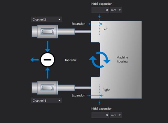
Turbine supervision instrumentation – Figure 8 VM600Mk2 configuration software screenshot (VibroSight PROTECT) showing a dual channel housing expansion measurement (differential). The expansion on each side of the housing is measured and the monitor can display these absolute values., as well as the difference between the two – useful for determining when a single foot is stuck and so-called “armored casing”.
VP valve position
Large valves are used for the admission of steam to the AP turbine. Multiple valves are often arranged in a call “valve rack”, where the cams drive lever/plunger arrangements that open and close the valves due to their substantial size. Figure A 9 illustrates this situation.
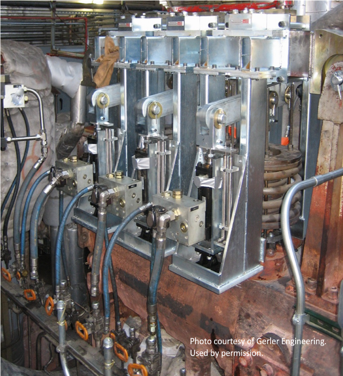
Turbine supervision instrumentation – Figure 9 A typical steam turbine valve rack (on).
One method of measuring valve position is by using a rotary potentiometer which senses the rotational position of the cam.. These potentiometers are rare and mainly of historical interest.. More frequently, LVDTs are used to measure valve spool position (course).
Measuring the valve position is thus similar to measuring the expansion of the casing., in which LVDTs are used to measure linear motion. However, environmental conditions in the valve rack are normally more aggressive, both in terms of temperature and humidity, due to the hot steam passing through the valves.
For this reason, for valve position measurements, AC LVDTs are typically used instead of DC LVDTs with their lower temperature ratings sufficient for enclosure expansion measurements.
In the past, valve position measurements were normally incorporated into the TSI system. At the moment, However, this is becoming less common and measurements are normally fed directly into the turbine control system.
The valve position in the TSI system is, therefore, most often found in upgrade situations where an older ETI rack (como or MMS system from Vibrometer) is being replaced by an identical set of measurements on a newer hardware platform, like the VM600Mk2. The measurement is treated as a quasi-static channel type in the MPC4Mk2 module and can be done on any of its 6 channels available. However, as valve position does not require dynamic signal processing, it is often allocated to the auxiliary channels 1 or 2.
ECC eccentricity
Since steam turbine rotors are quite long, if they remain at rest for a long time, deflect due to gravity. Instead of allowing the turbine train to stop turning completely when the steam turbine is not in operation, it is usually placed on a rotating gear (sometimes called spinner, hoist gear or bus gear) that slowly rotates the train at speeds as low as 2-3 rpm, thus preventing the development of a flexible arch.
Anyway, a certain magnitude of arcing will be present at the rotors and, during startup, the length of this arch must be carefully monitored and controlled. This measurement is known as the rotor eccentricity. – or simply eccentricity – and is represented in Figure 10.
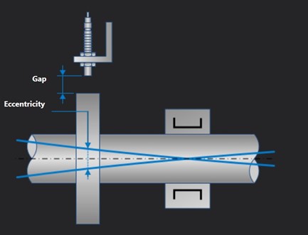
Turbine supervision instrumentation – Figure 10 Screenshot of VM600Mk2 configuration software (VibroSight PROTECT) which represents a measurement of the eccentricity. Unlike radial vibration, which is measured very close to the location of a bearing, eccentricity is measured at a location where any residual curvature of the shaft will be quite pronounced.
Eccentricity measurements are taken to ensure the amount of bending is not excessive., allowing safe starting within acceptable vibration limits. In severe cases of curvature, when the machine was not stopped due to excessive eccentricity, operators have been known to bend a rotor beyond its elastic limits, resulting in a permanently bent shaft instead of a temporary bend.
Eccentricity measurement is usually done close to the high pressure turbine casing., well away axially from a bearing or nodal point and, therefore, where eccentricity will be most pronounced and easily observed (usually on the AP turbine tube extension in the frontal pattern). The figure machine 1.1 is, therefore, typical, since the eccentricity measurement is carried out at the extreme outer edge of the AP box, as shown in Figure 1.2.
ZS zero speed
As mentioned in the section on eccentricity, shaft bending is a concern in large steam turbines and, therefore, a rotating gear is used instead of allowing the rotor to come to a complete stop when the turbine is not running.
The rotating gears are normally engaged when the rotor slows down to an acceptable speed. – normally less than 100 rpm in some turbines and in others much slower and in the order of only 2-3 rpm. At these speeds, if a conventional phase reference signal is used, once a turn, to indicate the speed, it may take until 30 seconds between pulses measured by the speed indicator probe.
For this reason, a toothed wheel or a gear is usually used, which allows you to update the speed more frequently and measure it more accurately (a full turn of the shaft is not necessary to detect the change). See Figure 11.
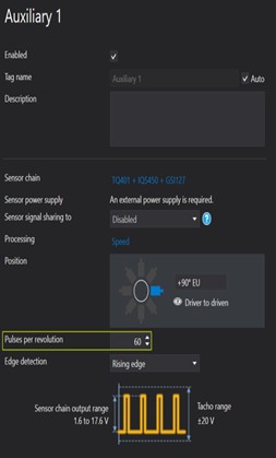
Turbine supervision instrumentation – Figure 11 VM600Mk2 Setup Software Screenshot (VibroSight PROTECT) which represents a tachometer measurement of a gear 60 teeth. This setup is typical of zero velocity measurements, where appropriately rapid updates must be available – beyond what is available from a once per revolution phase marker when a machine is running at very low rpm.
The zero speed measurement is simply an underspeed alarm that detects when the rotational speed has dropped below an acceptable threshold and the rotating gear can thus be safely engaged.. Since the measurement is so critical and the implications of starting a rotary mechanism before the rotor has slowed down sufficiently are so substantial, it is customary to use redundant probes and compare the rpm measurements of each to ensure they agree within a configurable percentage.
3 Turbine supervision instrumentation – Conventional measurements
All machines with radial and thrust bearings (thrust) fluid film, are best monitored by a set of measurements that are not unique to large steam turbine generators. As such, cannot be correctly designated by measurements “IS”, but are part of the total set of measurements for these machines. These are seen below.
relative vibration of shaft X-Y XYSRV
These measurements (figure 12) are performed with a pair of proximity probes orthogonal bearings mounted close to each radial bearing.
The orthogonal arrangement of the probes allows measurements to be taken in each plane of vibration.
Given that probe mounting directions are rarely truly horizontal and truly vertical, are usually referred to as X and Y instead of horizontal and vertical. Not only can vibration be measured in each direction, as well as a composite measurement showing the orbit of the vein.

Turbine supervision instrumentation – Figure 12 – Measurements of vibrations relative to the X-Y shaft are carried out using two orthogonal proximity probes. These observe the instantaneous position of the shaft within the bearing clearance., relative to the mounting location of the probe (usually the bearing box).
The major axis of the orbit is known as Smax and is a common parameter calculated by the monitoring system to assess the severity of the vibration. – particularly in European countries. See also the figures 13.1 e 13.2.
When only a single probe is used, the measurement is simply referred to as relative shaft vibration (the X-Y is omitted). This is generally not recommended because you are only able to observe the vibration in one direction and it is, therefore, “blind” for vibration on the orthogonal axis – regardless of its severity.
A single spacecraft also limits diagnostic capabilities because an orbit can no longer be generated along with the highly useful information it contains..

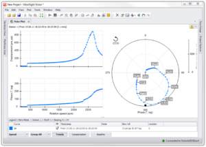
Turbine supervision instrumentation – Figure 13.1

Turbine supervision instrumentation – Figure 13.2 VM600Mk2 Setup Software Screenshots (VibroSight PROTECT) representing a vibration measurement relative to the X-Y shaft. This configuration creates a pair of channels capable of returning not only individual amplitudes, but also composite measurements, like smax. In this example, probe X is in the channel 1 e to probe Y is in the channel 2. The screenshot below shows the composite signal from the two probes, resulting in an orbit of the shaft. The major axis of the shaft orbit is known as Smax and is often used as a protection parameter..
Absolute bearing vibration / Absolute shaft vibration BAV/SAV
Thermal power plants normally employ multi-level buildings with the turbines on the top floor., allowing piping and associated steam intake to come from below the turbines. Such designs often result in conforming support structures where seismic vibrations substantial (bearing box).
While this is not limited to large steam turbine generators, it's quite typical of them. for such machines, it is advisable to measure both the relative vibration of the X-Y shaft, as mentioned in the previous point, as well as bearing housing vibration
Although measurements of bearing housing vibration are often performed in the “top dead center” of the bearing cover and, therefore, on the pure vertical axis (Figure 14), it is also possible to mount seismic sensors (that is, speed or acceleration) orthogonally on the same axis as the(s) in the end(s) of relative proximity to the shaft in the same bearing.

Turbine supervision instrumentation – Figure 14 – Measurement of absolute bearing vibration involves the use of a seismic sensor. (speed or acceleration) to measure bearing housing vibration (or “tampa”) in relation to free space; measures only the movement of the box – not the movement of the shaft.
In this provision, so-called measurements can be carried out “absolutes of the vein”, representing the subtraction of the seismic movement of the cap from the relative movement of the shaft.
Since the proximity measurement probes measure the combined relative movement between the bearing housing and the shaft, subtracting the housing movement from the bearing, it is possible to isolate the movement of the shaft in relation to the free space and not in relation to the bearing housing. For this reason, is thus described as an absolute shaft measurement. See Figure 15.

Turbine supervision instrumentation – Figure 15 – Screenshot of VM600Mk2 configuration software (VibroSight PROTECT) showing a pair of channels used to make an absolute shaft measurement. It consists of a proximity probe in the channel 1 and a speed sensor in the channel 2.
axial position (impulse) AP
The axial position measurements (see Figure 16) are used to determine whether impulse forces are occurring in the expected direction (that is, normal) or in an abnormal direction (that is, contrary) and that the bearing is adequately restricting axial movement of the shaft.
Thrust bearing failures can be especially catastrophic because they allow rotating and stationary parts to come into contact along the entire length of the shaft, thereby potentially damaging the entire rotor and stators of the machine.
Since this measurement is of vital importance as part of the machine protection strategy, typically incorporates two probes in a dual voting arrangement (2 in 2), where both probes must detect excessive movement before sounding an alarm. This poll is required by the API standard 670 for machine guarding systems and is recommended good practice for all machines. There is also a configuration option for 1-of-2 voting.
USE: When axial probes are rigidly attached to the machine housing, instead of thrust bearing structure, the effect due to the movement of the bearing structure is eliminated from the measurement. This is known as the rotor position., as it indicates the amount of movement relative to the machine housing and not relative to the bearing to which it is connected (and that you can also move). Contrary to rotor measurements in frames that undergo significant thermal expansion, rotor position measurement is assumed to be in frames that exhibit negligible thermal expansion. When the box itself may experience thermal expansion/contraction, the probe must be fixed on the foundation of the machine and not on its box.
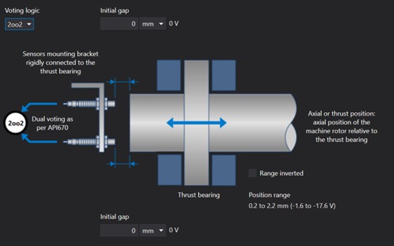
Turbine supervision instrumentation – Figure 16 VM600Mk2 configuration software screenshot (VibroSight PROTECT) showing a dual poll axial position measurement (2oo2). 1oo2 voting is also a configurable option, using the selection of the appropriate voting logic in the upper left corner of the screen.
PT phase trigger
Similar to a timing mark on the crankshaft of an automobile engine, a sensor of phase shot provides a reference pulse that allows you to determine the position of rotation (degrees of rotation) of came in a precise instant.
This measurement allows you to calculate the vibration phase for all radial vibration probes and bearing cover sensors., as well as filtered measurements for multiples of machine running speed, such as 1X, 2X, ½X, etc.
The phase is very useful for vibration diagnosis and is, de facto, so useful that diagnostics is greatly impaired if this phase reference information is lost. For this reason, many users prefer to install redundant phase trigger probes so that, in case the primary probe fails, secondary is available.
Unlike many other measurements, such as a faulty radial vibration sensor, a faulty phase trigger sensor affects almost every other sensor in terms of available machine diagnostic capabilities. The shaft surface discontinuity for a phase trigger is often a keyway (projection) or a keyway (notch), but sometimes it consists of a slot made specifically for this purpose.
In large steam turbine generators, care must be taken to place the mark in a location where the thermal growth of the rotor does not cause the discontinuity to move outside the observable field of the probe, as can happen when the measurement takes place at the extreme end of the shaft, near the generator or driver.
If there is no other suitable location, the discontinuity must be long enough that any expansion or contraction does not allow the discontinuity to leave the probe's observable field.
A phase trigger sensor can also be used for velocity measurements., but the refresh rate and accuracy will not be as good as with a multi-tooth wheel, as used for zero speed measurement. However, this is normally not a concern for machines running at medium speeds, like a steam turbine 3000 your rpm 3600 rpm that drives a generator.
Turbine supervision instrumentation – Figure 17 A phase trigger sensor (or phase reference) provides a once-per-turn signal used for phase measurements.
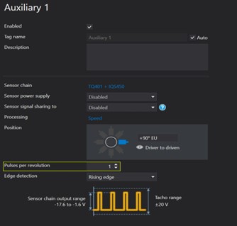
Figure 18 VM600Mk2 Setup Software Screenshot (VibroSight PROTECT) that shows a phase reference measurement. In contrast to the configuration in Fig. 11 (60 impulses per revolution), a true phase trigger should only have a single pulse per revolution.
T bearing temperature
Excessive load on fluid film bearings – radial ou axial – can melt the babbitt material and cause major problems beyond the bearing, if not detected.
It is customary to incorporate temperature sensors – RTDs or thermocouples – in the bearing to measure pad temperatures and ensure they remain within acceptable limits, well below babbitt's melting point.
At the moment, temperature measurements are often taken directly in the turbine control system, where other protection parameters may also reside.
However, many users still prefer to put these measurements in the vibration monitoring system. For these, the VM600Mk2 can directly accept both thermocouples and RTDs via special temperature monitoring modules. 8 channels.

Figure 19 A typical tilting pillow thrust bearing with two built-in temperature sensors.
Overspeed
Overspeeding a turbine is one of the most potentially catastrophic scenarios a machine can withstand.. Since the centripetal forces acting on the rotating parts, such as turbine blades and couplings, are related to the square of the speed of rotation, a turbine is designed to withstand only small excursions (20-30%) beyond its rated speed – whether designed for 50 Hz (3000 rpm) or 60 Hz (3600 rpm).
When excessive centripetal forces occur, the blades can break free from the rotor, becoming projectiles and being able to pierce the box. Besides that, rotors can bend, couplings can come loose and the machine can literally “explode” (Figure 20).

Figure 20: Consequences of catastrophic overspeeding of a steam turbine generator 64 MW. A massive one-piece portion of the shaft spool (inset) pierced a wall many meters away during the event, coming to a stop at the men's locker room.
In the case of a steam turbine, this may be especially consequential, because hot, high-pressure steam is no longer confined within the pressure vessel (machine box) and can inflict tremendous damage to people and property when it escapes.
for all these reasons, overspeed measurements are very specialized, involving multiple layers of redundant tachometers and sensors, often in a mood of 2 in 3 to reach SIL level 3.
The VM600Mk2 platform tachometer channels are not intended, therefore, over speed measurements. Instead, existe a plataforma SpeedSys300 (Figure 21), specifically designed for turbine overspeed applications.

Figure 21 – O SpeedSys 300 by Vibro-meter is a SIL rated speeding detection system 3.
Industry best practice is to separate the overspeed system from the turbine control system, as well as the machine's vibration system. SpeedSys300 was thus designed as a standalone platform for overspeed protection..
3 Turbine supervision instrumentation summary
The VM600Mk2 is specially designed to meet the measurement needs of most types of industrial machines., including gas and steam turbines. For steam turbines in power generation service, specialized TSI measurements are required and the VM600Mk2 has channel types to meet each of them. As the VM600Mk2 uses an innovative design of “single module” to provide all types of channels in a single module (MPC4Mk2), spare parts are drastically reduced.
In addition to machine protection functions, the new MPC4Mk2 incorporates built-in condition monitoring capabilities, providing all necessary on-machine measurement functionality in a compact 6 channels that occupies only a single slot on the VM600 chassis.
Users can, like this, trust Vibrometer to fully meet the needs of these important machines with a second-generation platform that will provide reliable protection and condition monitoring for decades to come.