antifriction metal bearings
This article provides an introduction to anti-friction metal bearings and their lubrication..
This article belongs to a series, which constitutes the support material for the course on vibration analysis in turbomachinery. Links to the other articles can be found on here.
1 – Introduction
Bearings are used to prevent friction between parts during relative movement.. the machines, fall into two main categories:
- roller bearings
- antifriction metal bearings.
2 function of bearings
The main function of a bearing is to carry load between a rotor and the machine structure with the least possible wear.. This bearing function exists in almost all occurrences of everyday life., from the watch on the wrist, to auto and disk drive on computer. industry, the use of roller bearings is specialized in low and high speed rotating machines.
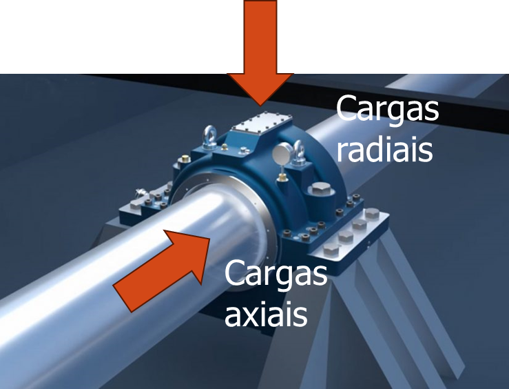
Figure 1 – Functions of the bearing
Lubrication technology goes hand in hand with understanding anti-friction metal bearings and is an integral part of bearing design and application..
Since they have a fluid film with significant damping, plain bearings have a strong impact on the vibration characteristics of machines. The types of machinery in focus, range from small high-speed spindles to motors, blowers, compressors, fans and pumps to large turbines and generators to some paper mill rollers and other large low speed rotors.
3 When to use anti-friction metal bearings
There are many applications where roller bearings are the best choice.. Normally, the smallest engines, pumps and fans use roller bearings. Paper mill rollers often use specialized large spherical bearings. Clearly, roller bearings are best for these applications.
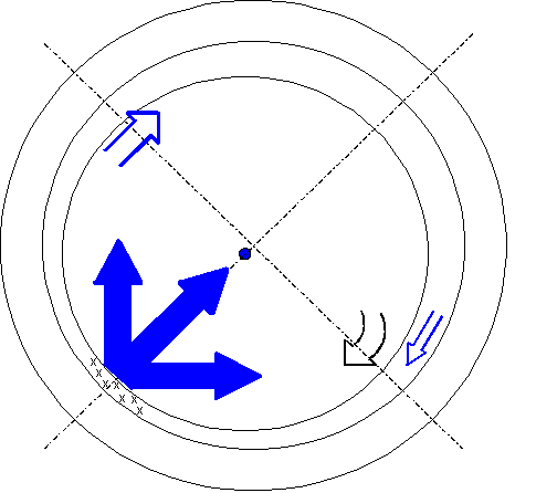
Figure 2 – Fluid film bearing
However, when the size of a bomb (or fan or motor, etc.) becomes big enough and fast, enter a gray area. There are roller bearings successfully used, in this conditions, but as speeds increase and temperatures rise, rotor dynamics often become a concern and critical speeds are encountered. It is at this point that cushioning is needed and anti-friction metal bearings become increasingly necessary..
In turbomachines, consideration should be given to using anti-friction metal bearings if they operate above the 3000 rpm or if the machine exceeds the 500 CV (375 Kw). From 1000 HP (750 Kw), all machines, except in very special cases, must be equipped with anti-friction metal bearings specifically designed for this service. There are exceptions, Of course, and the decision where to apply what type of bearing is, ultimately, socket for each machine individually based on good engineering practices and experience.
4 Advantages of anti-friction metal bearings
The main advantage of an anti-friction metal bearing is, often, considered as the absence of contact between the rotating parts and, therefore, endless life. in a strict sense, this is true, but other complications make this a secondary reason for using these bearings. during startup, there is momentary metal-to-metal contact and foreign matter in the lubricant or excessive vibration can limit the life of an anti-friction metal bearing. for these reasons, Special care must be taken when selecting and implementing lubrication and special lubrication techniques must be applied. vibration control.
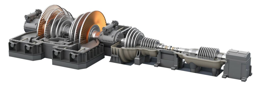
Figure 3 – Steam turbine from a generator set
The most important aspects of the health and longevity of an anti-friction metal bearing are:
- your selection,
- Installation,
- Lubrication
- The alternating hydrodynamic loads imposed on the bearing surface by the relative vibration between shaft and bearing.
Some of the main advantages of anti-friction metal bearings are:
- provide cushioning. Damping is required to pass through a critical speed. Damping is also necessary to suppress instabilities and subsynchronous vibrations;
- Ability to withstand shock loads and other abuse;
- reduce noise;
- Reduce transmitted vibrations;
- Electrical insulation of the rotor to earth;
- Very long service life under normal load conditions;
- Wide variety of bearing types for specific applications.
The lubricant used provides these functions to all bearings:
- Eliminate the heat generated in the bearing;
- Clear the cargo area of debris.
Some disadvantages of anti-friction metal bearings are:
- higher friction (power loss) than in bearings;
- Susceptible to particulate contamination;
- It cannot work for an extended period if the lubricant is lacking, for example, a failure of the lubrication system;
- Less accurate radial rotor positioning.
The use of bushings is also an advantage in many applications with regard to maintenance.. Most anti-friction metal bearings are split and it is not necessary to remove the impeller for inspection and replacement.. Although split roller bearings are also available, are expensive and not common. Fatigue damage to plain bearings is usually visible at an early stage and allows for better diagnosis of failure modes, so that corrective measures can be taken to prevent recurrence.
5 Basics of anti-friction metal bearings
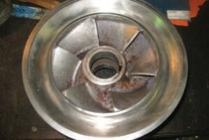
To illustrate the basic nomenclature, geometry and introduce ideas of how anti-friction metal bearings work, the simplest bearing will be analyzed, called a plain or sleeve bearing. The following figure is a photograph of a plain bearing. A steel base material is coated with a Babbitt material and drilled to a circular diameter equal to the shaft diameter plus the desired clearance.. Slots are cut in the parting line to admit oil.
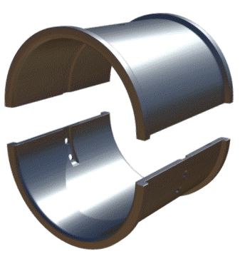
Figure 4 – Plain or bushing plain bearings
at zero speed, shaft rests on bearing at bottom dead center. As soon as spindle rotation starts, the came “gets up” on a layer of oil. On anti-friction metal bearings, lubrication is required between a pair of surfaces with relative motion. There is always a convergent wedge that forms due to the relative velocities of the surfaces and the viscosity of the lubricant to support the applied load.. An oil pressure film develops with equal and opposite force vectors to the applied load. A surface drags the lubricant, usually an oil, for a convergent slit. As the available space in this crevice decreases, the fluid develops a pressure gradient, or pressure hill. When the fluid comes out of the slit, the increased pressure helps push it out the other side. The following figure presents a simple diagram of this situation..
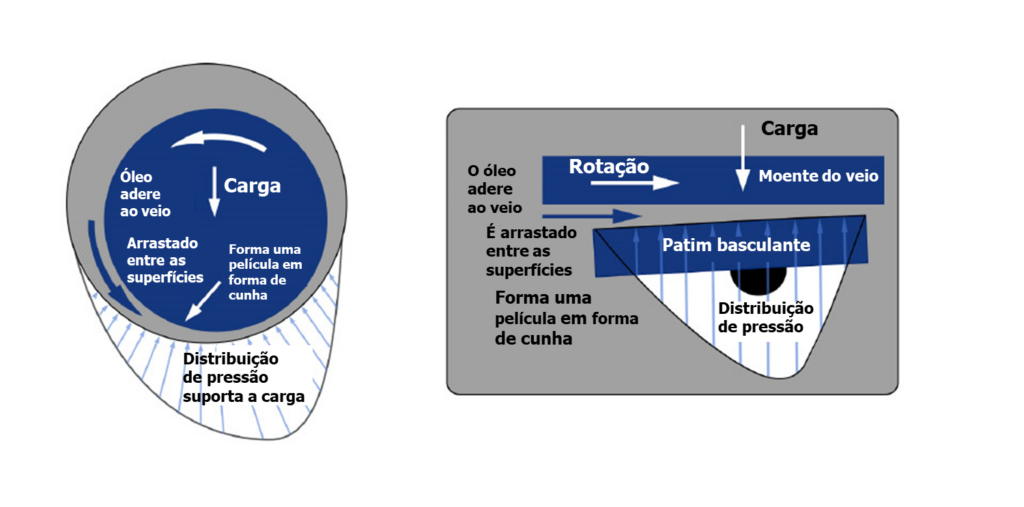
Figure 5 – Development of oil wedge between shaft and bearing
Lubricants can be any fluid, including gases. Initially, some of the lubricants used were tallow, the lard (animal fat), vegetable oils and whale and fish oils. Even water can be used under certain conditions.. Petroleum mineral oils have evolved from simple distillates to complex formulations with special additives.. Synthetic lubricants have also been developed, mainly polyalphaolefins and esters. Silicones, glycols and other fluids are also used in special applications. There is no ideal or universal lubricant, all are compromises that adapt to a given situation. Applications range from heavy loads at low speed to light loads at high speed. at an extreme, solid lubricants may be required and, in the other, gas bearings may be required. Obviously, most applications are in the middle, where grease and oil lubricants are used. This article about plain bearings, be limited to the light oil lubrication found in most turbomachinery.
6 Chumaceiras nomenclature
The terminology used here is presented schematically in the following figure.. The symbolic notation and definitions are as follows:
- Rj = Spindle journal radius
- Rb = Bearing radius
- Cb = Bearing radial clearance = Rb – Rj
- h = Radial clearance as a function of the angular position where the clearance is measured
- hmin = Minimum oil film thickness
- e = Eccentricity – the distance between the center of the bearing and the center of the shaft
- e = e/Cb = Eccentricity Ratio – se for zero, the shaft is centered; watch for 1, the shaft touches the anti-friction metal
- Centerline = Line connecting the center of the bearing and the center of the shaft
- φ= Attitude angle = Angle from the -Y axis to the centerline
- Ω or ω = Direction of rotation and speed in rad/s
- W = Weight
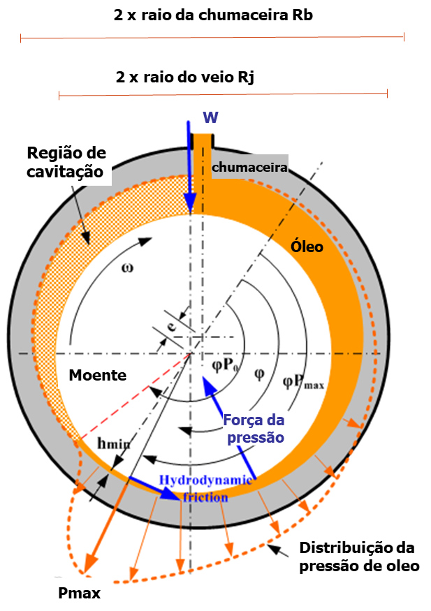
Figure 6 – Nomenclature of chumaceiras
In the example of anti-friction metal bearings, the load is supported by a region of high pressure oil, as shown in the previous figure. Each line in the pressure profile represents an oil pressure vector at the centerline of the bearing. The sum of the vertical components equals the applied load and the horizontal components cancel out for equilibrium. Oil inlet holes are placed in areas of minimum pressure.
7 bearing performance
bearing performance – Rigidity and damping
While the stiffness and damping provided by an anti-friction metal bearing are crucial, there are other design factors that must be considered to understand how it works.
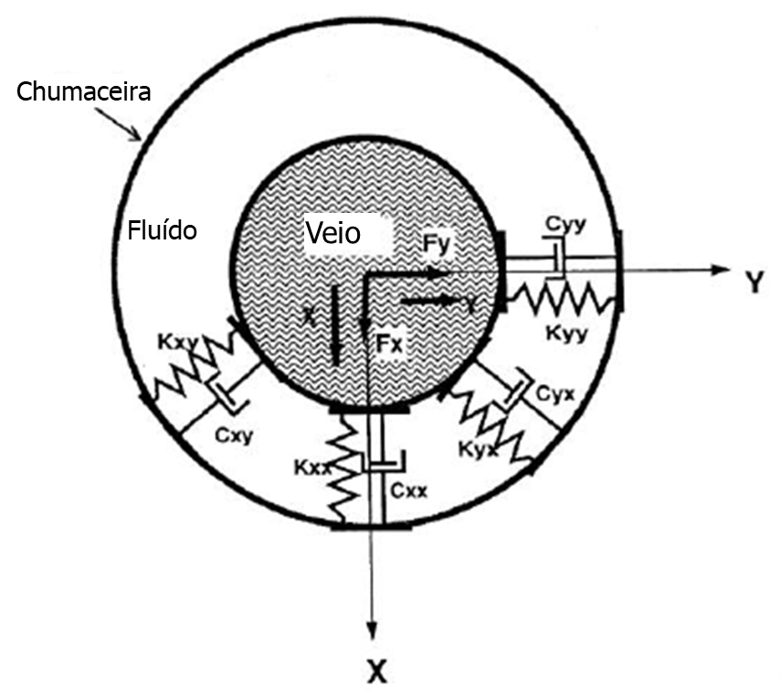
Figure -7 – Bearing stiffness and damping
Notice-I know that:
- Kxx is an abbreviation for horizontal stiffness
- Kyy means vertical stiffness.
bearing performance – eccentricity
For example, if the eccentricity is too high, there is a risk of metal-to-metal contact and higher dynamic loads being transmitted to the Babbitt, causing premature fatigue. If the eccentricity is too low (the journal is almost centered), the machine can become more easily unstable. Eccentricity is a function of both speed and load.
bearing performance – attitude angle
The attitude angle between the vertical axis in the direction of the load and the line of centers also changes with speed. A graph of this angle with the eccentricity plots the location of the shaft centerline as the velocity changes., as can be seen in the figure below.
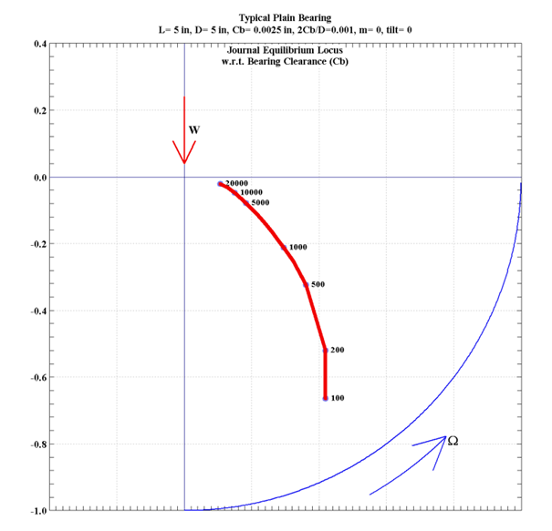
Figure 8 – Variation of the attitude angle between the vertical axis in the direction of the load and the center line1
bearing performance – Temperature
One of the most important parameters is the maximum temperature that will be generated in the oil film. This is consistent with power losses for a given bearing and will be slightly higher than the actual temperature measured with an RTD or thermocouple at the bearing shell.
Although it is possible to operate plain bearings above 90°C, normally try to keep the maximum oil film temperature below that, due to babbitt's loss of fatigue strength. If possible, a good design will have the maximum oil film temperature less than 80°C to allow for some leeway for transient events.

Figure 9 – Bearing temperature measurement
bearing performance – Minimum film thickness
Minimum oil film thickness, and a very important parameter. To follow, the h/c ratiob is represented as a function of velocity with a constant load. This relationship is between the minimum film thickness as a percentage of bearing clearance. If we know that the radial clearance is 5 mils (127 microns), then the minimum film thickness can be calculated at any speed. For a radial clearance of 5 mils, in this case, the h would be about 1 thousand (25 microns) a 100 RPM and more 4 mils (100 microns) above 5000 RPM.
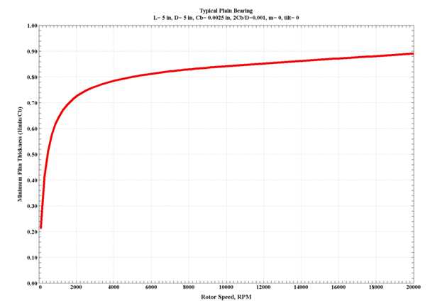
Figure 10 – The minimum oil film thickness in a plain bearing at constant load1
8 – Lubrication
Viscosity is the most important factor for anti-friction metal bearings.
There are two forms of viscosity terminology and numerous units associated with these measurements..
Absolute or dynamic viscosity is the relationship between shear stress and the resulting shear rate as a fluid flows.. The more a fluid resists shear, the thicker it is and the greater the absolute viscosity. This is measured in Poise (or Centipoise).
The kinematic viscosity is the absolute viscosity divided by the specific gravity. The most common unit of measurement is the Centistoke., abbreviated cSt.
Viscosity ranges
The Table 2 is a list of typical applications and the viscosity ranges found in various applications. This list is by no means complete nor is it intended to exclude other oils in similar services.. Viscosity varies significantly with temperature and the variation is highly non-linear.. It is often performed, mixing oil bases to reduce these effects
Table 1 – Typical viscosity ranges for various applications
| Application | Viscosity range (cSt) |
| Clocks, light instruments, high speed spindles | 2-20 |
| Turbochargers – turbines, compressors, etc. | 4-30 |
| bearings | 8-300 |
| High load, low speed oil film bearings | 8-100 |
| Reciprocating engines and compressors | 10-300 |
| high speed gears | 50-150 |
| low speed gears | 50-600 |
| worm gear | 200-1000 |
lubrication regimes
The friction factor (e, consequently, the loss of potency) is a function of viscosity, load and speed. This factor was quantified by Richard Stribeck, a German engineer who carried out exhaustive friction tests on 1902. then, there was a lot of research to try to find the best combinations of materials and lubricants that would provide the lowest coefficient of friction. The friction factor is represented as a function of ZN/P, where Z is the viscosity, N is the speed and P is the load. This is a non-dimensional equation.
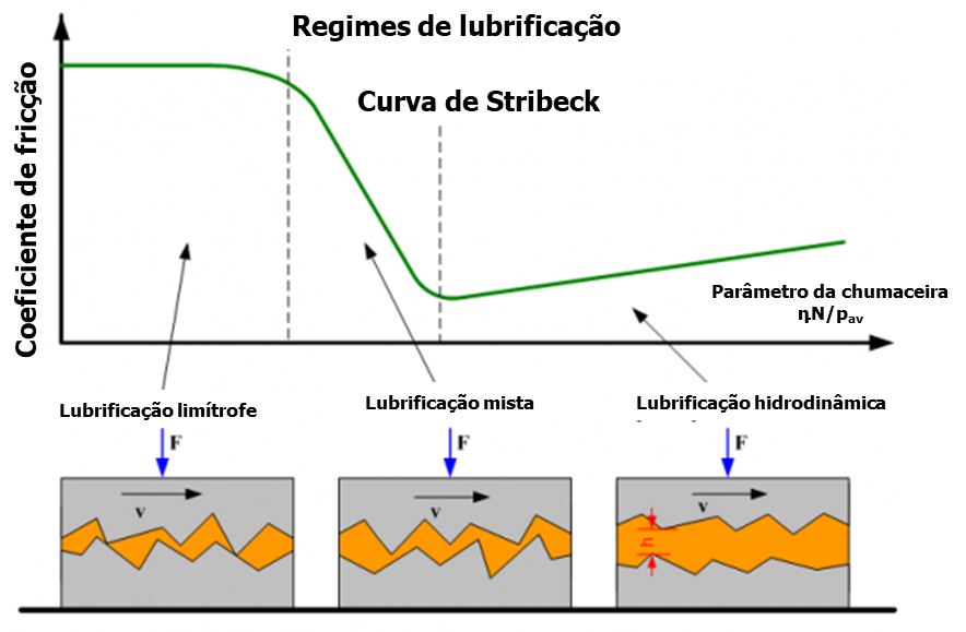
Figure 11 – Stribeck curve that relates the friction factor to the viscosity, speed and load
Normally, The aim is to minimize friction., so you want to be somewhere in the central region of the Stribeck curve, in hydrodynamic lubrication. Since speed and load are often fixed for a given machine, a suitable lubricant viscosity must be chosen. Other factors that affect this decision include temperature and supply pressure., the generation and removal of heat, Corrosion resistance and material compatibility.
9 – Antifriction metal bearing materials
Since the bearing is usually much less expensive than the shaft, is considered sacrificial, if necessary. Besides that, a low coefficient of dry sliding friction between shaft and bearing material, is important for the start and stop conditions.
Virtually every conceivable engineering material has been tried as support material.. Primitive man used wood or even stone. Later, the iron, copper and leather were applied to relatively low speed shafts. In the seventeenth century, Robert Hooke advocated the use of steel shafts with steel bushings. “fate metal”, essentially bronze, to replace the practice of using wooden blocks in cast iron. There has been extensive research into the best slip material to use..
In 1839, Isaac Babbitt patented several high tin and lead alloys that are similar to modern formulations.. It is clear, its name is commonly used to describe many different support materials. the carbon, the graphite, the pottery, plastics and composite materials are all used today in some applications. Lead alloys have largely been phased out in due to lower strength and environmental considerations.. The most common fluid film bearing lining material used in turbomachinery today is high tin Babbitt.
These formulations are applied to a base material, typically steel, either by molding on a fixed support, either by rotation casting. Spin casting is supposed to create a better bond with the substrate, but it has been determined that impurities in the molten Babbitt can migrate to the Babbitt-base metal bond line during this process and weaken that bond. Although the Babbitt does not melt until the temperature is very high., lost nearly half of its tensile strength at room temperature, when it reaches a temperature of 100°C.
10 – Design parameters of anti-friction metal bearings
Designing a plain bearing for a specific application involves many considerations.:
- Available space
- Friction and heat generation
- constant specific load
- surface speed
- dynamic load (vibrations)
- L/D Ratio
- Day off
- base material
- grooves
11 – Design of anti-friction metal bearings
The simplest form of an anti-friction metal bearing is a smooth circular bushing with an inside diameter slightly larger than the outside diameter of the shaft.. The first bearings were often made by pouring Babbitt or white metal directly into a sleeve containing the actual shaft or a mandrel of the same size.. Then, the surface of the Babbitt was shaved to provide the desired clearance. The success of this procedure largely depends on the skill of the mechanic.. At the moment, Bearing scraping is strictly prohibited in most factories and is not recommended.. in the last century, many different designs of bearing profiles have been invented, but basic geometries are mainly limited by cost and ease of manufacture. Special circumstances may require unique solutions.
preload
beyond the break, the second most important factor of a bearing is preload. A preloaded bearing simply means that the center of curvature of the shaft does not match the geometric center of the bearing.. Preload can be thought of as the percentage of clearance reduction. No preload means, with a centered axis, an even gap all around and 50% preload would halve the clearance at the closest point. Typical industrial bearings have preloads in the range of zero to 50%. Preload is easy and inexpensive to add to a plain bearing. It's good to avoid getting too close to zero preload so that tolerances don't lead to ending up with a negative preload. Negative preload compresses the entry and exit of the skids, causing a scraping effect that will deprive the bearing of lubrication.
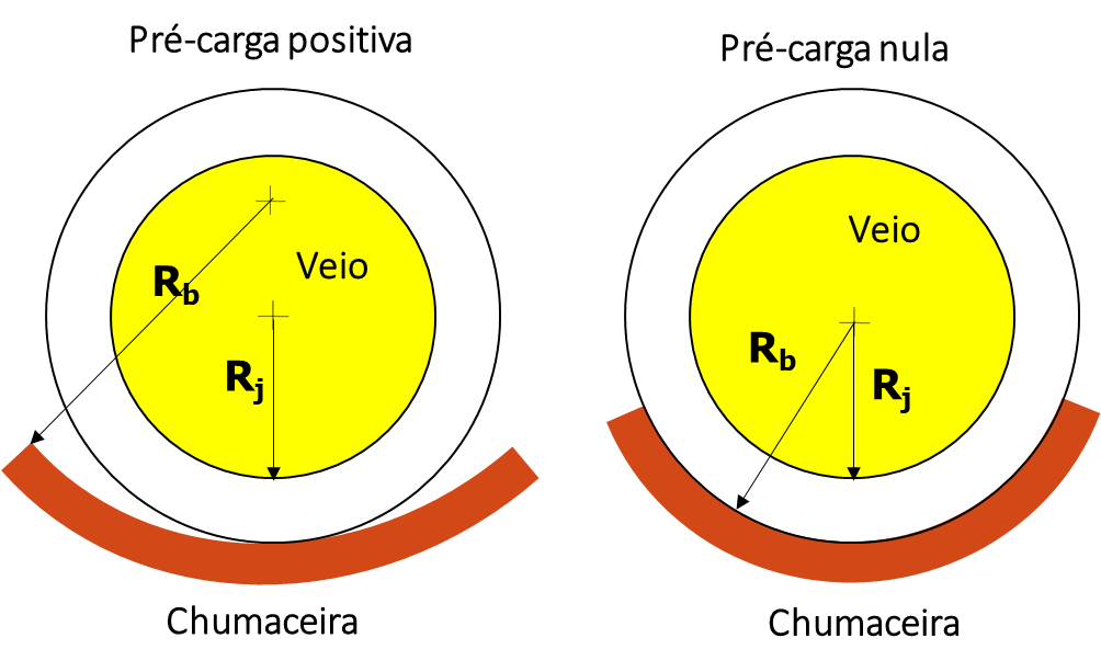
Figure 12 – Preload of a bearing
Detour
The other geometric parameter that is controlled is the deviation. When the closest gap is located in the middle of the bearing arc, this is the most common situation and is called deviation from 50%. The deviation can be increased beyond the 50%, but deviations less than 50% are not normal and are not recommended. Deviation is easily manufactured and difficult to detect. A deviation condition can be very useful to control stiffness and damping characteristics., as well as to reduce operating temperatures. Increasing the offset opens the input side of the bearing, admitting more oil. Bearings with deviation greater than 50% must not be rotated backwards, since this essentially creates a deviation of less than 50%. In practice, offset bearings always include a positive preload.
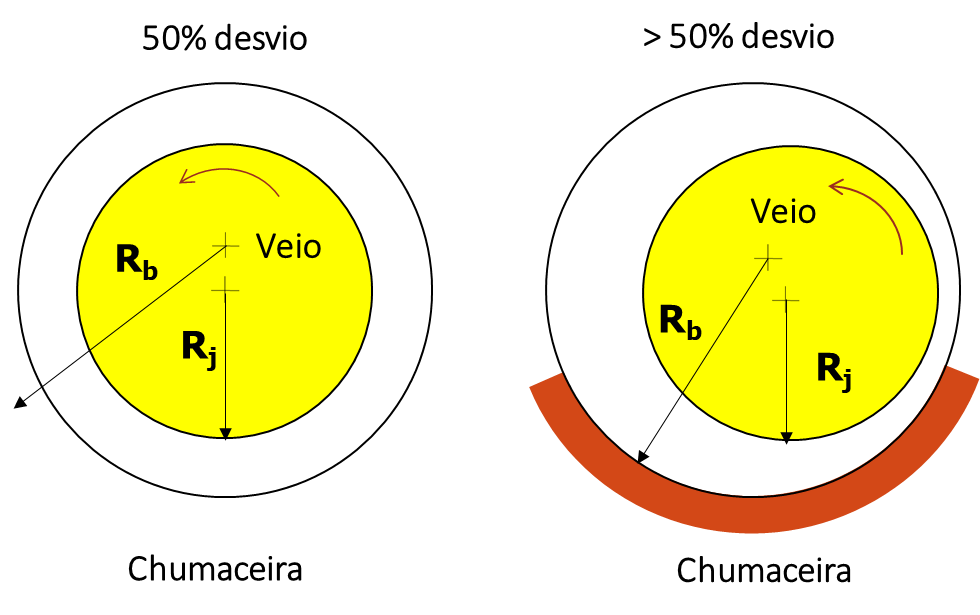
Figure 13 – Deviation of a bearing
12 – Types anti-friction metal bearings
As already mentioned, the simplest bearing geometry is a circular bushing. It turns out that this is suitable for many machines., but bad for many other applications.
Below are some types of bearings.
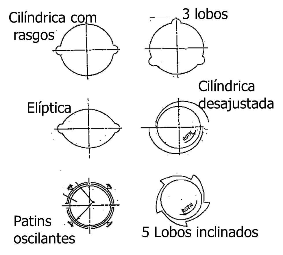
Figure 14 – Some types of bearings
Partial arc bearing
This is a bearing without a top half.. Used with known unidirectional loads and to save energy. Has reduced damping and less ability to resist vibration than a complete bearing. This type is not normally a good choice.. Sometimes, these are used to minimize friction and are most often found in electric motors.
Axial groove bearing
in its simplest form, it is a smooth circular bushing with two or more axial grooves for oil distribution. Normally, the four pillow model, but a larger number of pads can be used. Can be used when loading angle changes depending on operational variables. This design has slightly better stability than a plain bearing without grooves.
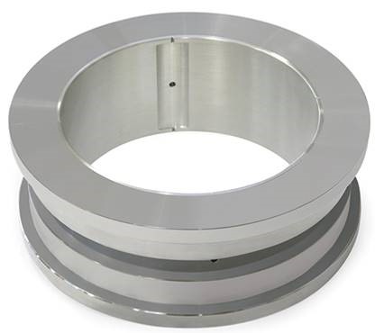
Figure 15 – Axial groove bearing
Elliptical chumaceira (or with lemon hole)
Elliptical bearings are very common. In some applications, is specified the “crush” of the bearing, which transforms a circular bushing into an elliptical arrangement. This bearing has better dynamic characteristics than a plain bearing and is more stable.. Normally, the horizontal clearance is 1,5 times to twice the vertical clearance (33 a 50% of preload). The angle of the division between the halves can be reoriented to obtain the best load and damping capacity.. Dynamically, this is a highly asymmetric bearing. Stiffness in the tightest gap direction is often an order of magnitude less than that in the tight gap direction.. Damping is also significantly less in the direction of maximum clearance..
Chumaceira of lobes
Lobed bearings can refer to any number of lobes with the designer taking advantage of the ability to control the geometry of each pad. This usually means adjusting the preload and offset for each pad.. The loading angle can also be selected for optimal conditions.. The three lobe bearing is the most popular configuration, but its manufacture can be expensive. The designer can select the clearance, the preload and offset of each pad, as well as the orientation of the load on the pad, between the pillows or somewhere in between. The ideal configuration will depend on the dynamics of the rotor. Lobe bearings like these are very useful on vertical machines..
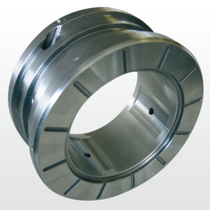
Figure 16 – Chumaceira of lobes
Offset bearing half
This is a very simple and very effective bearing in some applications.. It is a multi-lobe of 2 tablets with 100% of deviation. Pads are also almost always preloaded. It is easy to manufacture by drilling a plain bushing off center and turning the upper half. This bearing does not tolerate reverse rotation..
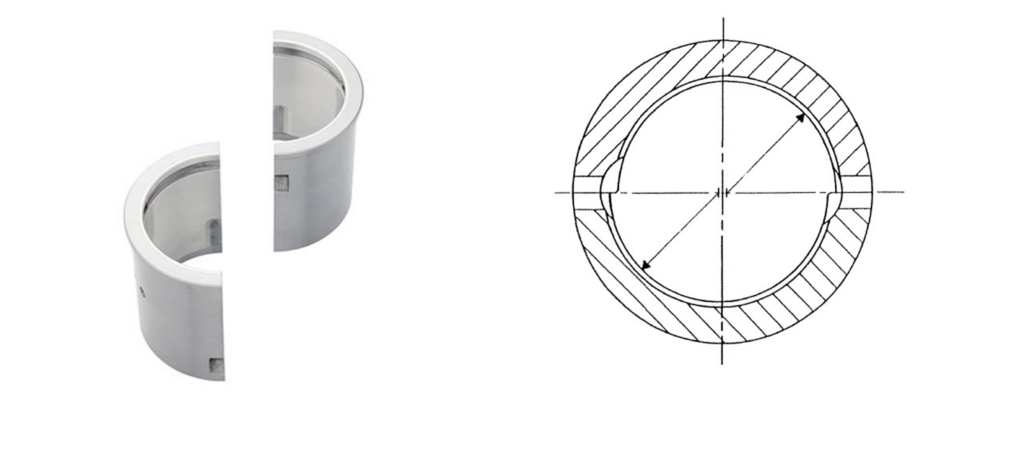
Figure 17 – Offset bearing half
pressure barrier bearing
Pressure barrier bearings, sometimes called pocket or step bearings, are plain bearings that can (rarely) have preload and even displacement. Normally, are two lobe bearings with a groove cut in the top half (or half without load) that creates an oil barrier. The circumferential velocity pressure of the oil that is, suddenly, impeded by the barrier, is converted to pressure. This pressure imposes a downward load on the shaft which will increase eccentricity and may stabilize the system.. This design also significantly increases the bearing stiffness and can cause the amplitude at critical speed and the amplification factor to increase.. This is, oftentimes, an excellent first design modification if the oil swirl (oil whirl) is found with plain bearings. Barrier height should be approximately the same as the bearing diametral clearance and up to three times that clearance. A deeper groove will have a significantly reduced effect. If these bearings wear out and the clearance increases, the effectiveness of the barrier will be reduced. Some designs now use multiple slots, particularly on vertical machines where there is no gravity load. This bearing is also unidirectional in rotation..
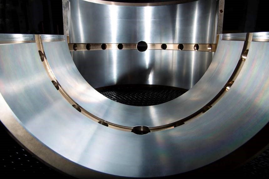
Figure 18 – pressure barrier bearing
tilting skid bearing
Sliding skid bearings are becoming the design favorite for turbomachinery. They are very robust, capable of being designed to optimize rotor dynamics and widely accepted as the best bearing you can get. These bearings also do not have significant destabilizing cross-coupling.. Can be costly and may not always be the best choice when all factors are considered. The following figure shows a typical modern tilting skid bearing.
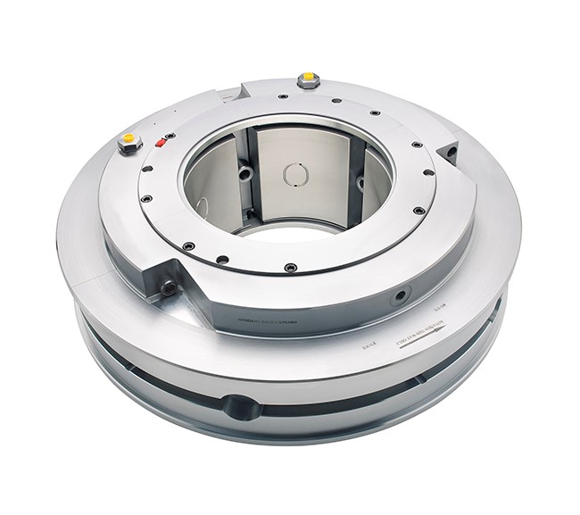
Figure 19 – tilting skid bearing
beyond the break, preload and displacement, the designer can choose the number of skates, different pivot arrangements, different types of end seals and load orientation. By choosing five-pad tilting skid bearings with load directly on a pad, horizontal and vertical stiffness will be significantly different from a four pad design with load between pivots which will have symmetrical characteristics.
Notice-I know that:
- Kxx is an abbreviation for horizontal stiffness
- Kyy means vertical stiffness.
Like this, for a particular machine, the various factors can be adjusted to obtain the desired frequency of critical speeds, the lowest critical velocity amplitude response, lowest running speed vibration and best rotor stability.
In the following figure, where the results of the calculations come from, indicates that the stiffness of the bearing 5 cushions, with load between pivots (LOP), will have a horizontal stiffness less than 1000000 LB/IN (17858 Kg/mm) and a vertical stiffness greater than 2500000 LB/IN (44645 kg/mm). However, if a bearing is selected 4 inserts with load between pivots (LBP), the horizontal and vertical stiffnesses are equal to about 2000000 LB/IN (35716 kg/mm) across the entire speed range.
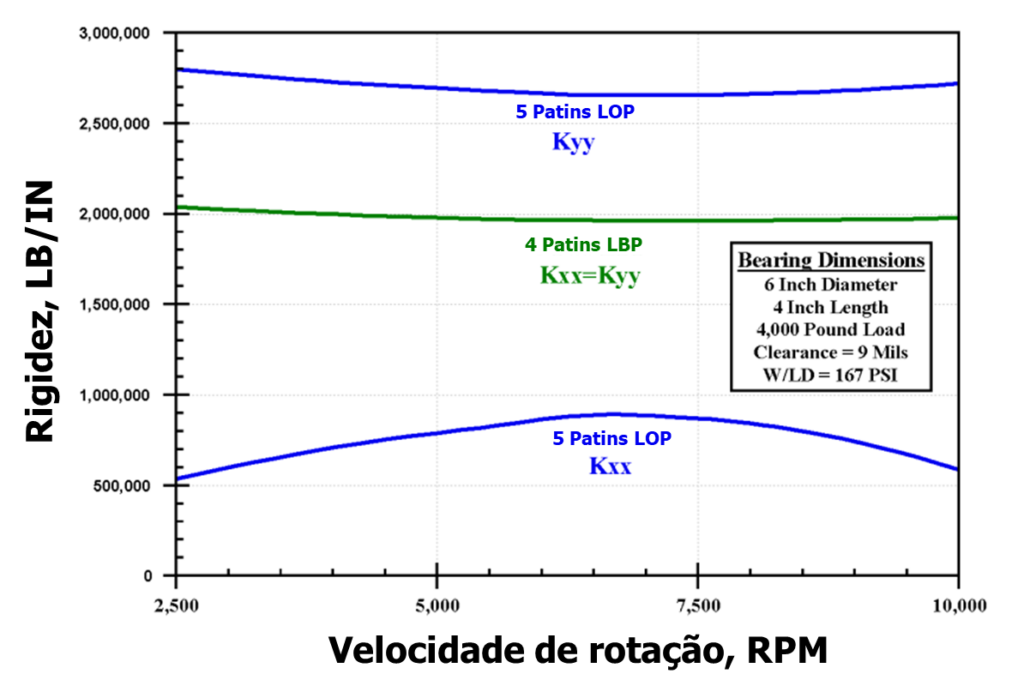
Figure 20 – Adjustment of bearing stiffness through load orientation and number of skids to fine-tune bearing stiffness1
Benefits
- Hydro-dynamically stable at high speeds
- Adapts to changing conditions
- Less sensitive to load direction or shaft misalignment than fixed profile bearings
- Optimized lubrication to minimize power loss and pad temperature
- Compact thrust and combined journal bearing models are available
- Advanced materials available to withstand high speeds, operating loads and temperatures, as well as special requirements of lubricants
special bearings
There are many other types of bearings. Even today, new advances in bearings are announced with some regularity.. Many of them are variations on very old concepts.. Special bearings fill niche markets where certain dynamic characteristics are required or space is limited, etc.
13 Comparison of results two calculations of bearing performance anti-friction metal – critical speeds
A first critical speed of a machine must often be overtaken until operating speed is reached.. Like this, rotor vibration amplitudes and amplification factor are important, especially where the highest amplitudes occur and where friction is most likely.
To illustrate the performance of different bearings in a turbo machine, each of the common types of fixed profile bearings was analyzed in the vicinity of the first critical velocity and the results are shown in the figure below.. In all cases, the L/D ratio of the bearings, slack and load were kept constant. the plain bearings, elliptical, of 3 lobes and displaced crescent showed similar amplitudes, while the pressure barrier bearing, much stricter, didn't have any performance. The following table is a summary of results for fixed profile bearings.
Table 2 – Results two calculations of dcritical speed performance for various fixed profile bearings1
| Bearing Type | critical speed, RPM | Maximum amplitude mils p-p | amplification factor |
| cylindrical | 4200 | 3,3 | 11,6 |
| Elliptic | 4100 | 2,8 | 9,2 |
| misfit cylindrical | 4075 | 2,9 | 9,2 |
| 3 lobos | 4000 | 3,2 | 11,4 |
| pressure barrier | 4250 | 9,0 | 30,0 |
With a very flexible rotor, like this example, changing the bearing type results in a change in the critical speed frequency of only about ± 3 Percent.

Figure 21 – Calculation of critical speeds for various fixed profile bearings1
The following figure compares the results of critical speed performance calculations with three plain bearing variations.. as before, the clearance and the L/D ratio were fixed. Each tilting skid bearing had a nominal preload of 20 Percent. Plain bearing response is included for comparison. Any of the tilting skid designs is significantly better than the plain bearing or any of the other fixed profile bearings.

Figure 22 – Critical speed performance calculation for various roller skate bearings1
The following table is the summary of the results.. The 4-pillow design has, de facto, an amplification factor below the threshold where the API considers this response peak to be a critical speed.
Table 3 – calculation of dCritical speed performance for various roller skate bearings1
| Bearing Type | Critical Speed RPM | maximum amplitude mils p-p | amplification factor |
| cylindrical | 4200 | 3,3 | 11,6 |
| 5 rocker skates, LOP | 4125 | 2,1 | 4,5 |
| 5 rocker skates, LBP | 4325 | 1,8 | 3,2 |
| 4 rocker skates, LBP | 4525 | 1,5 | 2,4 |
- LOP – load on pivot
- LBP – load between pivots.
14 Characteristics comparison of anti-friction metal bearings
In the table below you can see a comparison of the various characteristics of some of the bearings referred to..
Tabela 4 – Comparison of anti-friction metal bearing characteristics
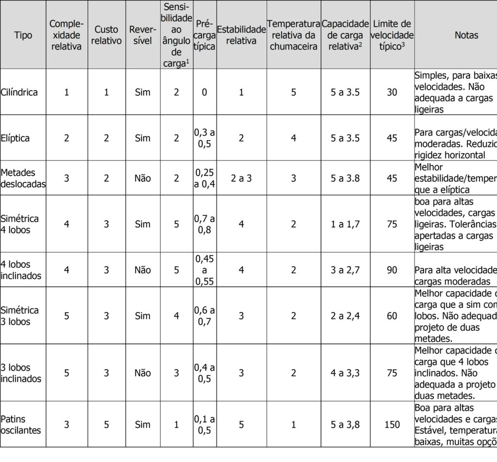
On a scale of 1 a 5: 1=low, 5 =Alta
- except low loads
- Load capacity depends on speed; Typical unit load, Mpa
- Speed limit depends on shaft weight.
15 set stability anti-friction metal bearing-rotor
It is important to see the dynamic stability of the rotor in conjunction with the bearings. The Oil Swirl (oil whirl) and the oil whip (oil whip) are relatively common phenomena. Instability usually means high levels of subsynchronous vibration. Oftentimes, an inclined skid bearing is installed to solve the problem, but that doesn't always work. Swing bearings do not contribute to instability, but a rotor can, even so, become unstable if the damping available is not sufficient to counter the destabilizing forces generated by seals and aerodynamic effects.
Any bearing change on a machine must be carefully evaluated for imbalance response., stability, temperature and maintenance considerations. There are now standard API paragraphs in RP684 for turbomachinery stability.
If we assume that the operating speed of a fictitious compressor is 9000 RPM and calculate stability with each bearing type discussed, the results in the following table indicate that a tilting skid bearing will be required. with some tweaks, half offset bearing designs and 3 lobes could possibly become stable, but only a little and nowhere near the stability provided by tilting pad bearing designs, all of which are very stable and could withstand significant cross-coupling. It should be noted that all of the tipper skid bearings listed here, have their pivots in the center of each pillow. If you enter the pivot offset, as is sometimes done for bearing temperature control, stability would decrease significantly because pivot displacement significantly increases bearing stiffness and reduces effective damping. All aspects of a machine's roto-dynamics must be considered when selecting bearings.
Table 5 – Comparison of stability of different types of fluid film bearings1
| Bearing Type | logarithmic reduction |
| cylindrical | 0,38 |
| Elliptic | 0,13 |
| misfit cylindrical | 0,03 |
| 3 lobos | 0,07 |
| pressure barrier | 0,21 |
| 5 rocker skates, LOP | 1,12 |
| 5 rocker skates, LBP | 1,05 |
| 4 rocker skates, LBP | 1,04 |
References
- Understanding Journal Bearings, Malcolm E. Leader, P.E., Applied Machinery Dynamics Co.