vibration isolation
vibration isolation
In this article, the topic of isolation of vibrations and rules of assembly, reviewing the theme of systems with a degree of freedom.
1 – DESCRIPTION OF A SIMPLE DYNAMIC SYSTEM
1.1 – Introduction
The systems that will be described below are as follows:
– Free movement with one degree of freedom, undamped
– Free movement with one degree of freedom, cushioned
– Forced movement with a degree of freedom, undamped
– Forced movement with a degree of freedom, cushioned
In fact, all physical systems have an infinite number of degrees of freedom.. However, a preliminary analysis will show that some components of the movement are, or negligible or uninteresting and can immediately be suppressed for the purpose of studying the phenomenon to be observed. This reduces the number of degrees of freedom to be studied.
1.2 – Basic concepts
A machine can be represented as a mass system mi, linked together by rigidity elements Ki, possessing a dampening There.
Let us remember these notions.
PULP
A mass is a rigid body whose acceleration, according to Newton's law, is proportional to the resultant of the forces acting on it.
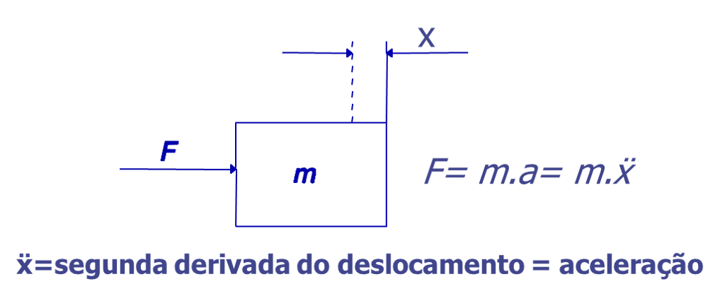
The unit of mass is Kg or Ns²/m.
RIGIDITY
Let's consider a linear spring:
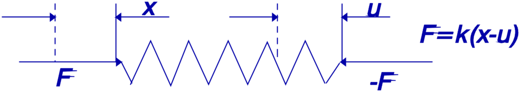
The variation in the length of the spring is proportional to the force applied to it.
F= K (x-u)
It is considered an ideal spring without mass. The force acting on one side is equal and opposite to the force acting on the other side. The proportionality constant k is called Spring stiffness..
The unit in which k is expressed is N/m.
DAMPING
Consider a viscous damping system like the one shown below.
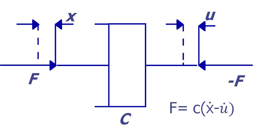
In viscous damping, the applied force is proportional to the relative speed of the application point.
![]()
The unit in which C is expressed is Ns/m.
Constant C is the damping coefficient, characteristic parameter of a shock absorber. It is considered an ideal massless damper. The force acting on one side is equal and opposite to that acting on the center.
The characteristic equations can thus be written in general as follows:
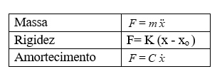
Other definitions that should be kept in mind are the following:
| free movement – | Movement with no external force |
| Undamped movement – | Movement without any dampening effect |
| Movement with one degree of freedom – | Movement only in one direction |
1.3 – Undamped Free Movement with a Degree of Freedom
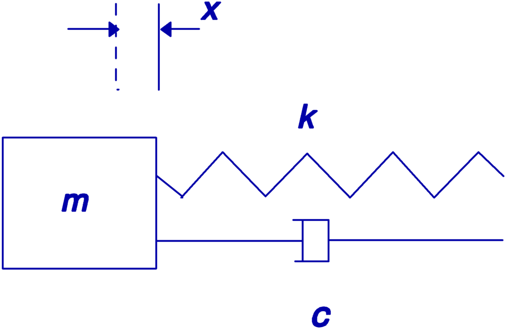
Consider, for example, a system consisting of a mass M connected to a fixed point by a spring K. Also consider that the mass can only move in one direction..
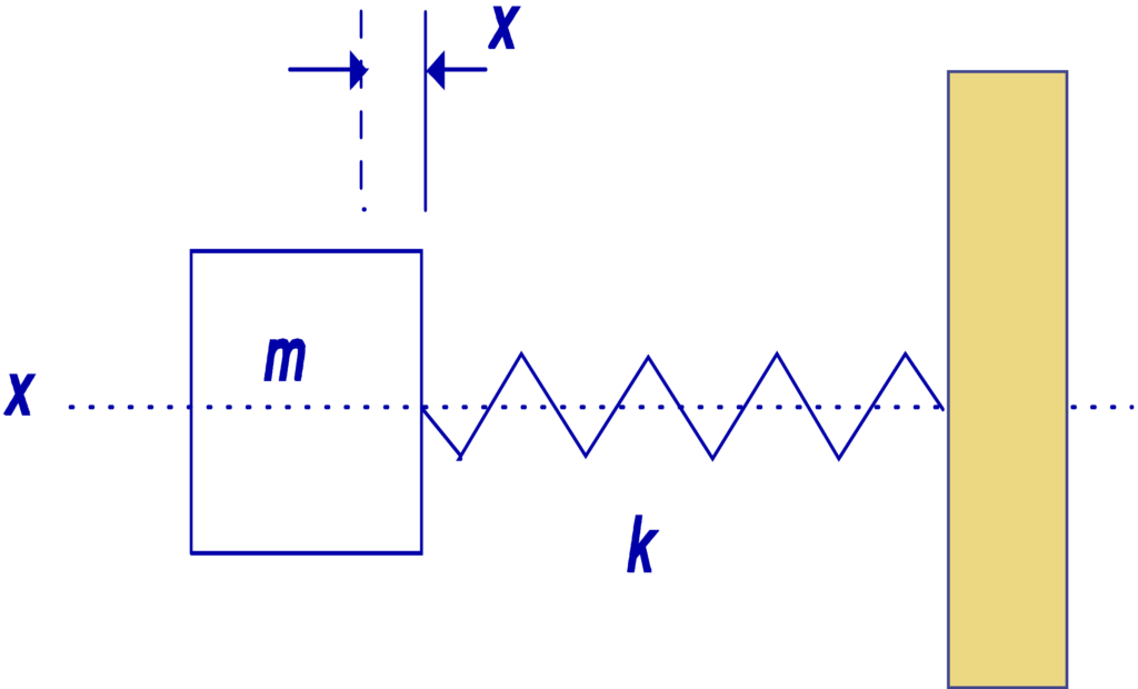
The equation that describes the movement of mass is:

The solution to this equation is:

A and B are two constants that can be determined from the initial conditions of velocity and displacement when t=0.
This movement is, therefore, sinusoidal type whose frequency is:

This frequency is called the Natural Frequency or Eigen Frequency of the system.
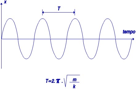
If there is no damping, this system will remain in motion indefinitely as you can see in the figure.
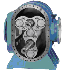
The example of forces in a rotating machine
The root cause of excessive vibration, most often found in machines is mass eccentricity. Mass eccentricity must be seen from the point of view of rotor symmetry, with regard to the recognition of natural behavior after conservation of angular momentum. The key point to recognize is that every object will naturally and freely tend to rotate about its true center of mass. (or axis of inertia) after applying any binary. This is driven by the inertia of the particles that make up the object when starting the circular motion of rotation.. The only way to prevent this rotation around the center of mass) is when some form of restraining force is imposed on the rotating object to keep it in some forced rotation, uncentered, which forces the true center of mass to translate laterally or rotate around the axis of forced rotation.
As a result of this imposed rotational asymmetry, a portion of the total energy supplied by the input torque to accelerate the rotor mass is converted into what is finally observed as “vibration” (more precisely, the radial deflection and lateral translation of the rotor journal axis). This energy manifests itself in the centrifugal force generated by the inertia of any part of the rotating mass that is asymmetrical., relative to the forced axis of rotation/rotation. This strength is what is typically recognized as “imbalance” during rotation. In combination with all the centrifugal force is the(s) strength(s) of reaction from the(s) Score(s) of restriction, maintaining this forced form of rotation.
1.4 – Dampened Free Movement with a Degree of Freedom
Damping is due to the emergence of passive forces that oppose speeds.. The viscous dampening, which is often found, has the great advantage of preserving the linearity of the equations; in fact passive forces are proportional to speed.
In case a damper is added between the mass and the fixed point, the characteristic equation of motion, in the absence of outside forces, is the following:

A coefficient called the Critical Damping Coefficient is normally defined and with the value:

According to the value of in relation to ξ, the equation will present several solutions:

A) X<1 – sub-damped movement
The solution of the equation is given by:

A = constant, function of initial conditions

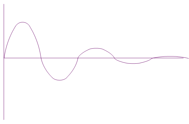
The evolution of this movement can be seen in the figure below. It appears that the system tends to return to its equilibrium position following successive oscillations. The oscillations are modulated by a decreasing exponential.
B) ξ=1 C=Cc (critical damping)
There are no oscillations and the system tends to its equilibrium position according to the following equation:
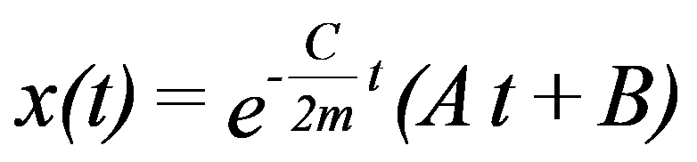
A and B are constants that depend on the initial conditions.
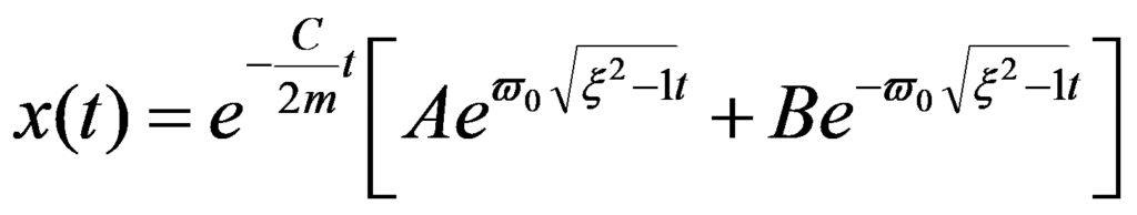
C) X>1 C>Cc over-damped movement
The motion is also non-oscillatory and is described by the following equation:
1.5 – Forced movement with an undamped degree of freedom and vibration isolation
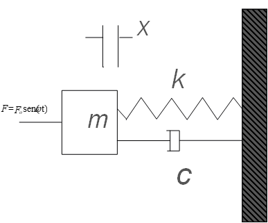
A very important case occurs when a periodic force is applied to a system..

This system can, for example, represent a machine of mass m connected to the ground by a structure with rigidity k.
The F force can be, for example, originated by a rotor imbalance of the machine that runs at the speed of rotation.
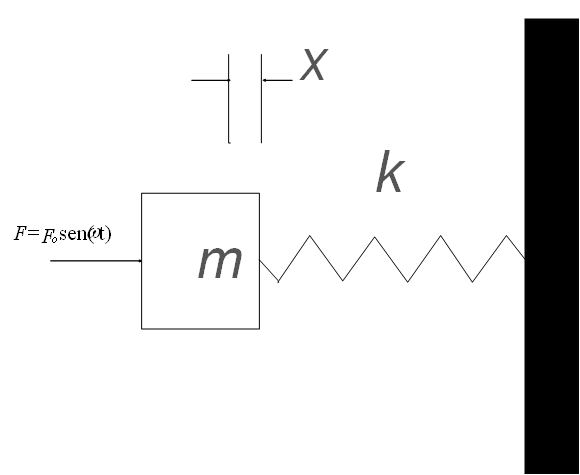
The characteristic equation of this system can be written as follows:

in which is the angular velocity of the driving force.
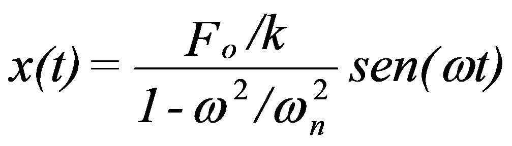
The solution to this equation takes the following form:
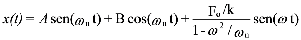
A and B are constants as a function of initial conditions.

The first two terms represent an oscillation in the Eigenfrequency ωn, in exactly the same way as determined for undamped free movement. It has already been seen that due to the damping effect, this oscillation disappears after some time. will remain, therefore, as the only stable solution a vibration forced to frequency ω whose amplitude will be:
Below you can see a demonstration on the influence of mass, at natural frequency, a system with one degree of freedom.
1.6 – Forced Movement with a Degree of Freedom with Damping
Consider a system similar to the preceding one, but now with a dampening device.
We can again write the characteristic equation of this system:

When damping is non-zero (C≠0), the displacement x can be roughly described by the following formulas.:
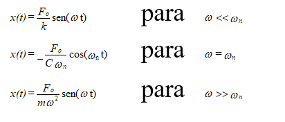
These are the stable solutions, not entering, therefore, account for the oscillations at the system's own frequency that disappear after some oscillations.
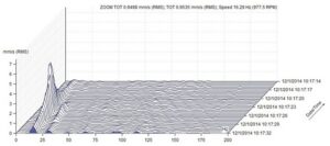
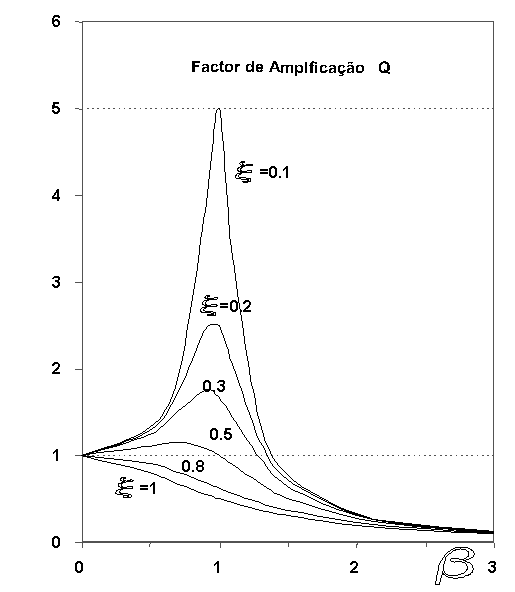
It appears that, when the frequency of the exciting force ω is equal to the eigenfrequency of the system (second case), amplitude is inversely proportional to damping. In case of weak damping, it can be dangerous to operate a machine at a speed close to the system's own frequency (commonly referred to as critical machine speed) due to the fact that vibration levels can assume very high values.
The relationship between the resulting response in amplitude x, and the displacement that the system would suffer if the force f were applied statically xst =f/k it's called the Q Amplification Factor:

where do you have:
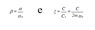
In the figure you can see the graphical presentation of this equation.
Below you can see a demonstration on the relationship between the excitation force and the range of motion., at various frequencies, in a system with one degree of freedom.
2 – THE ISOLATION OF VIBRATIONS
2.1 – Choice of Supports in vibration isolation
In the case of vibration isolation, the parameter that matters to consider is the one related to the force transmitted to the foundation or base of the machine. This parameter is the T transmissibility.
This parameter expresses the relationship between the force transmitted to the foundation Ft, and the force of excitement Fo.
The force transmitted to the foundation by the spring and damper is:
Transferability is given by:
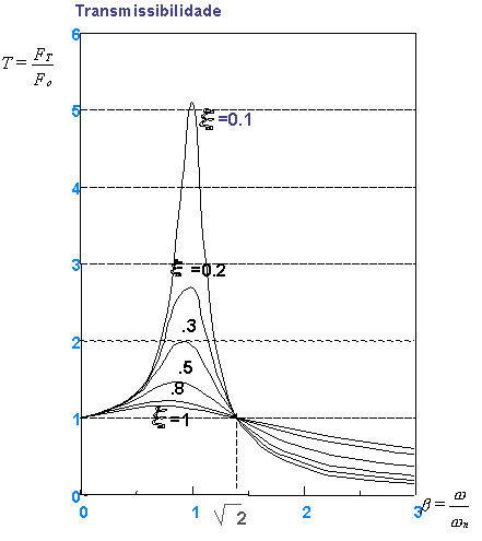
When the ω/ω relationn =1 (exciter frequency = system's own frequency), the resonance phenomenon occurs and the transmissibility is far superior to a. The amplitude of the system's response FT is thus superior to excitement F0; there is an amplification of the vibrations.
If system damping is null, the amplitude of the response when resonance occurs, becomes infinite.
In practice, C damping is generally lower than critical damping Cc..

Note that when resonance occurs, amplitude decreases when damping increases. for a relationship Ohn < √2, T is greater than one and the damping has a dampening function.
On the contrary, When Ohn > √2, there is an attenuation of power transmission, that is, when the system's eigenfrequency is lower than the forced frequency. In this case, however, damping tends to increase transmissibility. In the latter case it should not be concluded that damping becomes uninteresting; in fact its effect is not too great for Ohn > √2 , and can be compensated using less rigid springs (that is, reducing ωn). Furthermore, even if you do not intend to operate the machine in resonance, exceptional situations may occur in which this occurs and the existence of damping is essential.
Thus, the foundations can be isolated from a machine by inserting between them an elastic material such that the frequency of the machine on its support is much smaller. (at least three to four times) that the fundamental frequency of the periodic force. Of course the harmonics will be more attenuated the higher their order, especially if there is no great damping.
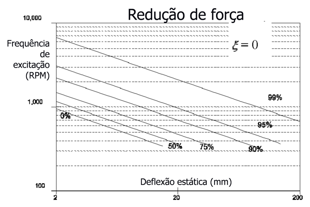
A parameter that is frequently found in the catalogs of anti-vibration supports suppliers is the Force Reduction.
force reduction (RF) = 1 – Transmissibility
To obtain adequate insulation, the Natural Frequency ωn must be low (β = ω / ωn >1) and the damping C must be reduced. Considering thus the case of null damping, the Transmissibility is:
The Strength Reduction will thus be given by:

how do you have:

Being the static deformation of a spring:

It is assumed that the Power Reduction will be:

The figure below shows the representation of this equation.
The efficiency of an insulation can be significantly reduced if the insulating system has rigid connections to neighboring structures., such as pipes, profiles, etc. any connection, must be as flexible as possible, both to isolate vibrations and to prevent connections from being damaged.
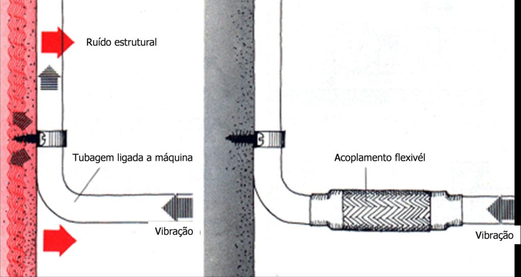
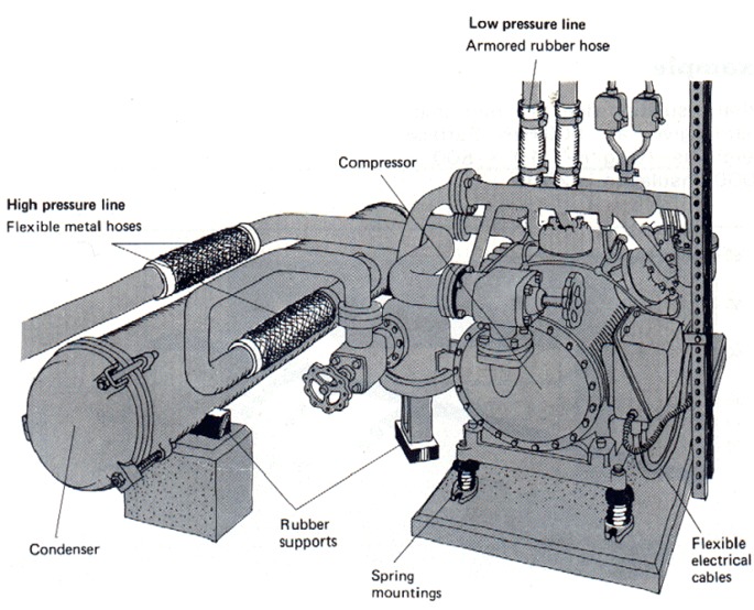
This type of anti-vibration insulation, in which it is intended that the vibrations generated in a machine do not propagate to the structure on which it is supported is called active insulation.
When the purpose of the insulation is to prevent environmental vibrations from reaching a particular installation, it is called passive insulation.
Some practical rules:
– An isolation of 80 % of the vibrations is enough
– Typically the natural frequency of the supported system should be 1/3 or 1/4 of the lowest frequency to isolate which is normally the rotation speed.
– The supports must be placed at the vertices of the base.
– After the supports are installed it must be verified that the static deflection is the same for all.
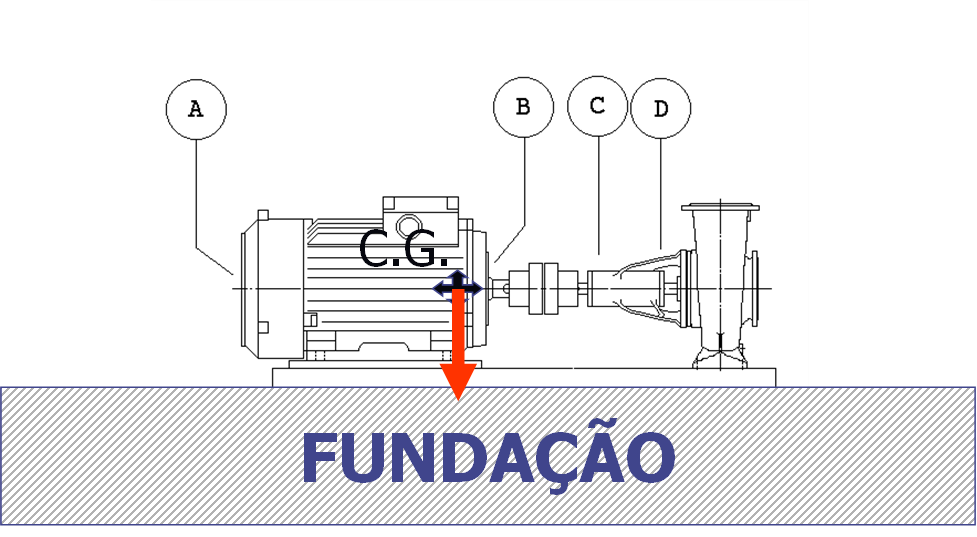
2.2 – The Assembly – Position of Supports in relation to the Center of Gravity and vibration isolation
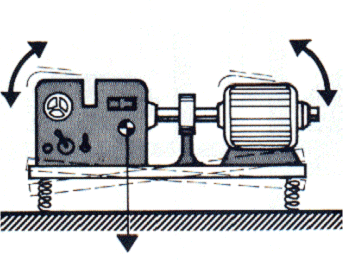
It is extremely important that the supports are correctly placed in relation to the center of gravity. In most cases all supports are similar and are excited equally in amplitude and frequency; so they are properly installed when they have equal deflection in all of them. It is therefore very important that the supports are distributed symmetrically in relation to the center of gravity and the main axes of inertia. Failure to comply with this rule may lead to excitation in the vertical direction., match movements in other directions.
occur, However, cases where this is not the case and, therefore, this has to be taken into account.
1º Case – Supports connected to fixed points on the machine
The stiffness of the supports must be adjusted..
P – Total load
P1,P2 – Load on supports P1 and P2
K1,K2 – Support rigidity 1 e 2
delta – static deflection
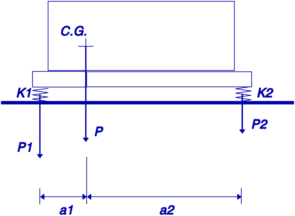
The equilibrium condition is:
a1×P1=a2×P2
so there is:
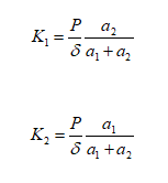
It will then have to choose supports with a stiffness as close as possible to K1 and K2.
2º Case – It is possible to choose the position of placement of the supports
Identical supports are used and placed asymmetrically so as to receive equal loads.
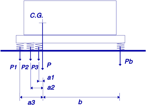
equilibrium condition:
equilibrium condition:
∑ (ai. Pi) = ∑ (bj.Pj)
If all supports are equal, they must be placed so that ∑ai=∑bj.
These formulas assume that the structure resting on the anti-vibration supports is rigid. If the structure is not rigid, the equilibrium condition can be found experimentally.
In this link you can see an example of the effects of a failure in vibration isolation.
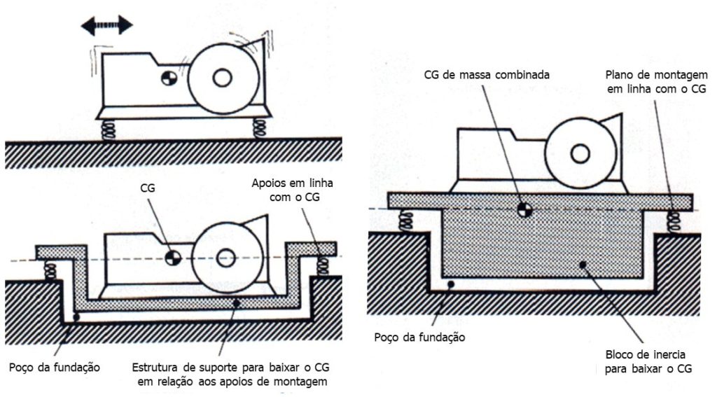
2.3 – The Block of Inertia and vibration isolation
Vibration isolation is achieved by the natural frequency and damping of the support system. So the function of the inertia block it is not isolate the vibrations.
The inertia block has several functions.:
– Reduce the amplitude of displacement due to vibrations by increasing the relationship between static mass and dynamic forces. IS, therefore, used when dynamic forces are large or you want to reduce displacement.
– Lower the center of gravity to obtain a better balance of the system in case of asymmetric mass distribution.
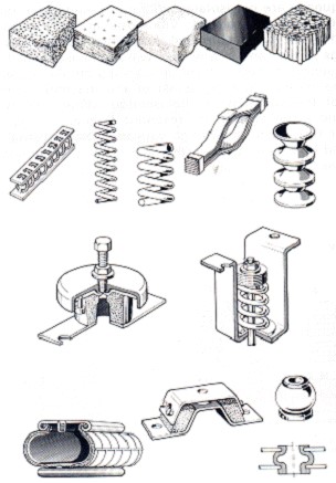
2.4 – Materials used in anti-vibration supports
There are many materials used in anti-vibration mounts for vibration isolation.. Here we are just going to talk about a few.
Cork
Cork is used both for compression and for cutting. Its properties depend on the frequency and load to which it is subjected. For larger loads it becomes more flexible.
springs
Springs are the elastic elements that allow greater static deflections, and in what, therefore, if they can reach lower frequencies. Have, Yet, very little damping also showing important displacements. Withstand very aggressive environmental conditions.
Rubber
Most rubber mounts work when cutting for greater flexibility. Its properties vary greatly with temperature and frequency.. Degrade in the presence of oil and gasoline.
Synthetic Elastometers
Elastometers have the advantage of being able to withstand tensile forces, to compression and to cut. However, it is only difficult to obtain assemblies with frequencies lower than 5 Hz.
3 – THE DAMPING OF VIBRATIONS AND THE INSULATION OF VIBRATIONS
Structures theoretically exhibit an infinite number of resonances. If subjected to variable frequency excitations or a wide frequency band of random vibrations, a certain number of resonances can always be excited.. Due to the fact that most materials used in engineering, such as the cases of aluminum and steel, have very little internal damping, it becomes necessary to reduce the effects of resonances with an external action. In the case of plates, rigidification is sometimes used.. However, this type of effect does not dampen the resonances.; yes transfer them to a higher frequency. If the resonant frequencies can be transferred to an area where they are not excited during normal use of the equipment, this solution may be acceptable.
On the other hand, in complex structures the transfer of resonances to other frequencies can lead to harmful consequences in some components. Thus, the most general solution for this type of problem is to apply some type of external damping to the materials..
External damping can be applied in several ways:
a) Through damping generated in surface friction
b) Through the surface application of a material with great dampening
c) Use of sandwich structures
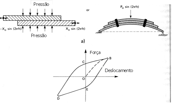
3.1 – Friction Damping
Friction damping is achieved by allowing two surfaces to slide over each other as shown in Figure. If there is no lubricant between the two surfaces, the dampening effect is caused by dry friction. The relationship between force and displacement, for this type of damping, is shown in Fig.22. The vibratory energy thus dissipated is given by the area within the curve B-C-D-E-B. This type of damping is used in bar springs..
3.2 – Application of Damping Materials
One of the simplest ways to introduce damping into a component of a vibrating structure is to apply a layer of a viscoelastic material., with important internal losses, on the component surface. This type of damping technique has been widely used in the automotive industry for many years.. The best known material for this purpose is called mastic, made from asphalt.
This type of materials, are made of polymers, and have optimal properties in a given frequency and temperature range..
To obtain the best damping of the structural component set + cushioning material, the internal loss factor and the modulus of elasticity of the damping material must be high.
The following approximate formula describes the damping characteristics of a treated surface:
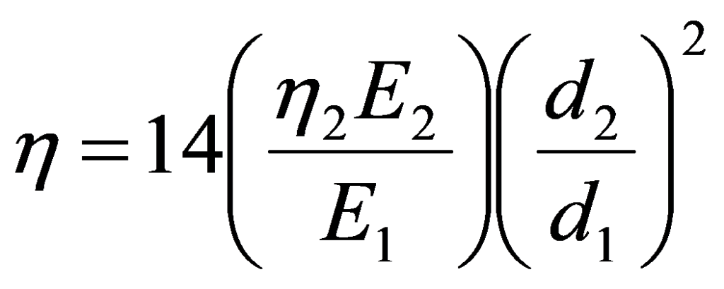
where do you have:

is the Loss Factor of the structural component combination + cushioning material
the2 = Damping material loss factor
E1 = Modulus of Elasticity of the structural component
E2 = Modulus of Elasticity of the damping material
d1 = Structural component thickness
d2 = Thickness of the damping material layer
A fact that becomes evident from this formula, is that the relative thickness of the damping material layer (d2/d1), plays a very important role in the resulting dampening. In practice, this ratio is chosen so as to be in the ratio of three to one.. It is also found that it is generally advantageous to apply a layer. (thick) of damping material instead of dividing the material into two layers, one on each side.
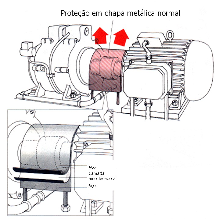
A third way to obtain damping in structural elements is through the use of sandwich structures.

There are several types of sandwich structures:
a) Structure with a layer of damping material covered by a metal sheet
b) Structure with a thin layer of viscoelastic material between two identical metal sheets
c) Structure with a thick layer of viscoelastic material between two sheets
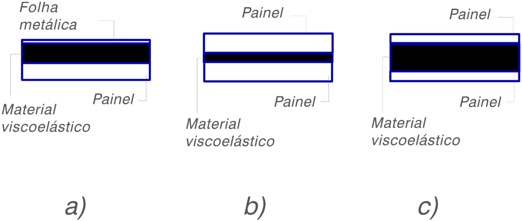
In sandwich materials the layer thickness of the viscoelastic material is not very important.. Most important parameter is the overall geometry of the structure (symmetrical, asymmetric); symmetrical structures have better vibration dampening characteristics. On the other hand, when the thickness of the viscoelastic material layer increases, also raises the temperature and frequency range at which optimal damping can be obtained.
In the following figure, see an example of the application of damping materials.