
Critical Speeds in Turbomachinery Shafts
This article addresses critical speeds in turbomachinery shafts, focusing on the physical foundations of the phenomenon, in analysis methods, in normative criteria and mitigation strategies.
1 · Introduction
All rotating machines have speeds at which they should not be operated. When the rotation frequency coincides with a natural frequency of the rotor–bearing–foundation system, the response to imbalance forces is dramatically amplified: It's called critical speed.
compressors, steam and gas turbines, Car turbopumps and turbochargers all share this problem, and its management constitutes one of the pillars of the rotodynamic project. This article covers the physical foundations of the phenomenon, the analysis methods, the applicable regulatory criteria and mitigation strategies available to the designer.
2 · What is it, in reality, a critical speed
A vein is never perfectly balanced. The center of mass is always away from the geometric axis of an eccentricity e, typically on the order of a few micrometers. When rotating at angular speed ω, This eccentricity generates a centrifugal force F = m·e·ω² that rotates in solidarity with the shaft — a synchronous excitation, whose frequency is exactly equal to the rotation speed.
Critical speed occurs when this synchronous excitation resonates with a natural mode of lateral vibration of the rotor. It is not a resistance limit of the material nor a “maximum speed”: is a dynamic amplification condition.

Figure 1 – Jeffcott Rotor operating below and above critical speed.
For the simplest model — the Jeffcott/Laval rotor, a disk in the middle of a massless shaft supported on two rigid supports — the first critical speed is given by:
ωc = √(k / m) Nc = (30/p) · √(k / m) [rpm]
with the bending stiffness of the bi-supported shaft given by:
k = 48·E·I / L³ I = π·d⁴ / 64
Addiction is revealing: stiffness increases with the fourth power of the diameter and falls with the cube of the length. A short, thick shaft pushes critical speeds upward; a slender shaft with a large gap between supports brings the first criticism into the operating range.
2.1 · Amplification close to resonance
The amplitude response r, normalized by eccentricity e, for a system with damping factor ζ and frequency ratio Ω = ω/ωc, is:
r / e = Ω² / √[ (1 − Ω²)² + (2·live)² ]
Three regimes emerge from this result:
- Below criticism (Oh ≪ 1): the deflection is small and the shaft “follows” the force; the disk rotates around its geometric center.
- In criticism (Oh ≈ 1): amplitude is limited only by damping, reaching r/e ≈ 1/(2g). With ζ = 0,02, This means an amplification of 25 times the original eccentricity.
- Above criticism (Oh ≫ 1): the phenomenon of self-centering occurs — the rotor starts to rotate around its center of mass and r/e → 1. It is for this reason that many high-speed machines deliberately run above the first critical.
the term 1/(2g) is the amplification factor (OF), the magnitude that standards use to classify the criticality of a resonance peak.

Figure 2 — Jeffcott Rotor Unbalance Response Curve
3 · Rigid rotors and flexible rotors
The most important operational distinction in the project separates two types of rotor according to their operating regime in relation to the first critical speed.:
Table I – Rigid rotors and flexible rotors
| Classification | operating regime | Typical examples |
| Rigid rotor | Below 1st critical speed | Industrial centrifugal pumps, fans, electric motors |
| Flexible rotor | Above 1st (sometimes from the 2nd) criticism | Steam turbines, multistage centrifugal compressors, aerospace turbopumps |
Flexible rotor forces it to cross critical during starting and stopping. This crossing is done quickly, with sufficient acceleration so that the amplitude does not have time to settle to the steady-state value — the start-up transient is, therefore, a design and operation phase with its own rules.

Figure 3 — Modal forms of a vein
4 Preliminary estimation methods
Before any finite element model, two classical approximations remain useful in the conceptual phase.
4.1 · Dunkerley method
Underestimates critical speed, producing a conservative result on the lower safety side:
1 / ωc² ≈ S ( 1 / ωi² )
4.2 · Rayleigh method
Overestimates critical speed; is based on the quotient between energies:
ωc² ≈ g · S (Wi · di) / S (Wi · di²)
at where
- Wiare the concentrated weights
- di the static deflections at the respective points.
Combined, both methods delimit the real critical speed from above and below, which is sufficient for sizing decisions at a preliminary stage.
5 · Factors that simple analysis ignores
The reality of a turbomachine is very different from Jeffcott's rotor. The following effects are decisive for the positioning and severity of critical speeds.
5.1 · Stiffness and damping of bearings
In a hydrodynamic bearing, the oil film behaves like a set of coupled, anisotropic springs and dampers, described by eight coefficients (kxx, kxy, kyx, kyy and damping counterparts) that vary with speed and load. The stiffness of the support is in series with that of the shaft, so flexible supports reduce criticism — but also provide cushioning that limits the peak. On real machines, bearing damping is the main source of system dissipation.

Figure 4 — Bearing dynamic coefficients
5.2 · Gyroscopic effects
Discs with significant polar moment of inertia, mounted on a console or away from the supports, generate gyroscopic moments that make natural frequencies vary with rotational speed. Modes separate in direct precession, whose frequency increases with ω, and retrograde precession, that goes down. There is no longer “a” natural frequency: there is a family of speed-dependent frequencies.

Figure 5 — Direct versus retrograde precession
5.3 · Foundation and carcass
One weak foundation, a degraded concrete base or poorly tightened bearings alter the critical speed of the installed assembly against that of the rotor calculated separately.
5.4 · Asymmetric stiffness and cracks
Key Features, non-circular sections or a propagating crack introduce angle-dependent stiffness, generating excitation at 2× rotation and zones of parametric instability.
6 · Campbell's diagram
How natural frequencies depend on speed, the synthesis tool is the Campbell diagram: natural frequency on the vertical axis, rotation speed on the horizontal axis. Natural frequencies appear as curves — ascending to direct precession, descending for retrograde precession — and the excitations as radial lines: the straight 1relative vibrations for the imbalance, 2relative vibrations for misalignment, Nbrelative vibrations for passing blades.
Each intersection between a natural frequency curve and an excitation line is a potential critical speed. The objective of the rotodynamic design is to ensure that none of these intersections fall within the continuous operating range.

Figure 6 — Simplified Campbell diagram without considering gyroscopic effects.
The following figure presents the Campbell diagram considering the separation between direct precession and retrograde precession.

Figure 7 — Campbell diagram taking into account the direct and retrograde precession resulting from gyroscopic effects.
6.1 · Rotodynamic analysis flow
The typical verification process involves the following steps:
- Gather rotor geometry, concentrated masses and material properties.
- Build the finite element model of the shaft, incorporating the dynamic coefficients of the bearings and the stiffness of the foundation and carcass.
- Perform the damped modal analysis as a function of speed and draw the Campbell diagram.
- Check the separation margins; if they are insufficient, resize diameter, span or bearing type and repeat.
- Perform imbalance response analysis and confirm that the AF is acceptable and that the amplitudes fit within the clearances.
- If necessary, add cushioning (squeeze film dampers, oscillating skate bearings) and repeat the response analysis.
- Conclude with stability analysis (logarithmic decrement) and validate the project.
7 · Normative criteria
The industry reference is the API 684, that supports the rotodynamic requirements of equipment standards — API 612 for steam turbines, API 617 for centrifugal and API compressors 610 for pumps. The essential principles are as follows.
7.1 · Separation margins
A critical speed must be at least 15% below the minimum continuous operating speed or 20% above maximum continuous speed. On variable speed machines, the requirement applies to the entire operating range.

Figure 8 — Separation margins between critical speeds and operating range
7.2 · Amplification factor criterion
Damping can dispense with the separation margin when it is sufficient to flatten the resonance peak:
Table II - Damping and separation margin
| amplification factor (OF) | Interpretation | Required separation margin |
| OF < 2,5 | Critically damped | Not applicable |
| 2,5 ≤ OF < 3,55 | Moderate cushioning | Reduced margin |
| OF ≥ 3,55 | Little damped | Full margin (−15% / +20%) |
7.3 · Response to imbalance and stability
The response to imbalances standardized values placed at the most unfavorable points for each mode, checking that the vibration amplitude remains within a fraction of the diametrical clearance of the bearings and seals. The logarithmic decrement of the modes in direct precession is also verified; a negative value indicates self-excitation and an unstable rotor, regardless of critical speeds.
7.4 · Forced resonance versus instability
It is worth separating two concepts that are often confused. Critical speed is a resonance forced, with amplitude limited by damping and proportional to the imbalance. Rotodynamic instability — oil whirl, oil whip, whirl induced by seals or internal friction — is a subsynchronous self-excitation, typically at about 0.42–0.48× the rotation, that grows until contact and does not depend on imbalance. Balancing the rotor better does not solve instability.
8 · Measurement and experimental verification
The model is validated on a real machine in three complementary ways.
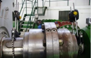
- Start and stop test com multichannel analyzers. Proximity Probes (eddy current) mounted in orthogonal pairs close to the bearings, they record the displacement of the shaft along the speed ramp. The data is presented in Bode diagrams — amplitude and phase of the component 1relative vibrations as a function of speed — and in polar/Nyquist diagrams. The unmistakable signature of a critical is the amplitude peak accompanied by a phase inversion of approximately 180°; phase is the most reliable indicator, more than the isolated amplitude.

Figure 9 — Bode diagram when passing through critical speed
- Impact test. Performed with the machine stopped, allows you to identify the natural frequencies of the installed set, including carcass and foundation.
- Spectral cascade (waterfall). Separates the synchronous component from the subsynchronous and harmonic components, distinguishing a resonance from a developing instability.

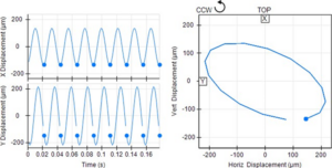
Figure 10 — Orbits and spectral cascade.
9 · Mitigation strategies
When analysis reveals a misplaced critical velocity, options are grouped into three families.
9.1 · Shift the natural frequency
Increase shaft diameter, reduce the gap between supports, add intermediate support, or change the mass and position of the impellers. Changing bearing stiffness — going from cylindrical bushing to oscillating runners, or modify the clearance and preload — moves the critical without touching the shaft.
9.2 · Add cushioning
Compressed film buffers (squeeze film dampers) in series with the bearings are the classic solution in aeronautical turbines: reduce the amplification factor to values that do not require separation margins and allow criticism to be crossed with controlled amplitudes. Active magnetic bearings offer real-time programmable stiffness and damping.
9.3 · Reduce arousal
The balance of precision — across multiple planes and at speed of service, in high-speed balancing machine — does not eliminate critical speed, but it proportionally reduces the amplitude in its passage. Complementarily, alignment is controlled, thermal warpage and gaps.
In operation, it is also restricted to staying in prohibited speed bands, programming the control system to traverse these areas with rapid ramps and never stabilize in them.
10 · Critical Speeds in Turbomachinery Shafts – Conclusion
Managing critical speeds cannot be solved with a formula. It involves the calculation of speed-dependent natural frequencies, the characterization of the dynamic support coefficients, checking the separation margins against the operational range, quantifying the response to imbalance and confirming the stability of the modes.
The practical rule that runs through the entire process is simple to state and demanding to comply with.: design so that no poorly damped resonance coincides with a continuous operating speed, and ensure that those that need to be crossed are done quickly and with sufficient cushioning.
An aspect that deserves increasing attention is that of variable speed machines driven by frequency inverters: by expanding the operational range, make it much more difficult to find a clear window between critical speeds, and transform damping — more than frequency positioning — into the decisive design variable.
References
- API Technical Report 684-1 (12nd edition, November 2019) — API Standard Paragraphs Rotordynamic Tutorial: Lateral Critical Speeds, Unbalance Response, Stability, Train Torsionals, and Rotor Balancing, American Petroleum Institute. Reference document that describes and clarifies the API standard paragraphs on lateral and torsional rotordynamics and the rotor balancing acceptance program, with basic material on the fundamentals of the topic (including terminology) and the rotor modeling used in this analysis.
- ISO 20816-1:2016 — Mechanical vibration — Measurement and evaluation of machine vibration — Part 1: General guidelines, International Organization for Standardization. Establishes general conditions and procedures for measuring and evaluating vibration in rotating parts, non-rotating and non-reciprocating complete machines, applying to both absolute and relative shaft vibration.
- Bently, D. E.; Hatch, C. T.; Grisly, B. (ed.) — Fundamentals of Rotating Machinery Diagnostics, ASME Press, 2002. Reference book that explains and demystifies the fundamental concepts for the effective diagnosis of faults in rotating machines, covering vibration fundamentals, phase and vibration vectors; diagnostic charts (timebase, Bode, polar, orbit, spectrum); rotordinâmica (rotor model, dynamic stiffness, vibration modes, stability analysis); and faults such as imbalance, fluid-induced misalignment and instability.
- Gents, G. — Dynamics of Rotating Systems, Springer, 2005. Formally defines critical speeds as the rotational speeds at which the frequency of one of the excitation forces coincides with one of the natural frequencies of the system, identifiable in the Campbell diagram by the intersection of the natural frequency curves with the excitation frequency curves — clearly distinguishing them from the speeds at which instability occurs, which should not be confused with critical speeds.